Table of contents:
- Do-it-yourself check, repair and replacement of the grinder anchor
- Grinder anchor device
- How to check the grinder anchor for serviceability
- How to check with a multimeter
- Checking the indicator of short-circuited loops (IKZ)
- Diagnostics with an anchor checker (choke)
- How to repair an anchor at home
- Repair: Elimination of insulation breakdown
- How to replace an old gearbox with a new one
- Author Bailey Albertson albertson@usefultipsdiy.com.
- Public 2023-12-17 12:53.
- Last modified 2025-01-23 12:41.
Do-it-yourself check, repair and replacement of the grinder anchor
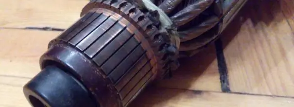
The grinder's anchor is most exposed to temperature, mechanical and electromagnetic loads. Therefore, it is a common cause of tool failure, and as a result, it often needs repair. How to check the anchor for performance and fix the element with your own hands - in our article.
Content
- 1 Angle grinder device
-
2 How to check the grinder anchor for serviceability
2.1 Standard diagnostics
-
3 How to check with a multimeter
- 3.1 Video: how the check goes
- 3.2 How to check the grinder rotor with a light bulb
-
4 Checking the indicator of short-circuited loops (IKZ)
4.1 Video: IKZ in operation
-
5 Diagnostics with an armature tester (choke)
5.1 Video: How to make a choke with your own hands and check the anchor
-
6 How to repair an anchor at home
-
6.1 Collector bore
6.1.1 Related Videos
-
6.2 How to rewind an anchor
- 6.2.1 Video: Remove the winding
- 6.2.2 Video: Winding Left and Right
- 6.3 Instructions for impregnation (including speed controller)
-
-
7 Repair: Eliminating insulation breakdown
- 7.1 Soldering the collector plates
- 7.2 Galvanic build-up of collector plates
-
8 How to replace an old gearbox with a new one
- 8.1 Video: how to shoot and what may be difficult
- 8.2 Video: Replacing the anchor
Grinder anchor device
The motor armature of the grinder is a conductive winding and a magnetic circuit, into which the rotation shaft is pressed. It has a drive gear at one end and a manifold with lamellas at the other. The magnetic circuit consists of grooves and soft plates coated with varnish for isolation from each other.
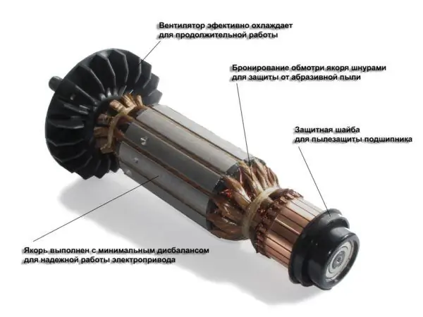
Angle grinder diagram
According to a special scheme, two conductors of the armature winding are laid in the grooves. Each conductor is half a turn, the ends of which are connected in pairs on lamellas. The beginning of the first turn and the end of the last are in the same groove, so they are closed on one lamella.
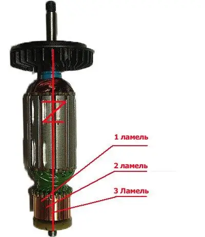
Collector lamellae
How to check the grinder anchor for serviceability
Types of armature malfunctions:
- Broken conductors.
- Turn-to-turn closure.
- Insulation breakdown to ground is a short circuit of the winding to the metal rotor body. It occurs due to the destruction of insulation.
- Desoldering of collector leads.
- Uneven manifold wear.
If the armature is faulty, the motor overheats, the winding insulation melts, the turns are short-circuited. The contacts connecting the armature winding with the collector plates are unsoldered. The power supply is cut off and the motor stops running.
Types of anchor diagnostics:
- visually;
- multimeter;
- a light bulb;
- special devices.
Standard diagnostics
Before taking the device for diagnostics, inspect the anchor. It may be damaged. If the wiring melts, the burnt insulation varnish will leave black marks or a specific smell. Bent and crumpled turns or conductive particles such as solder residue can be seen. These particles cause short circuits between the turns. The lamellas have curved edges, called cockerels, to connect to the winding.
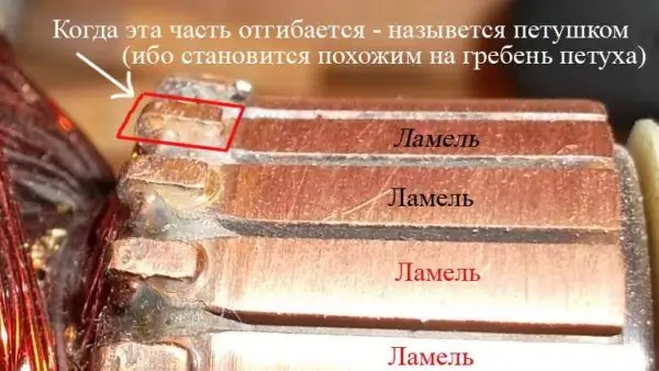
Cockerel lamella
Due to the violation of these contacts, the lamellas burn out.
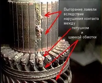
Lamella burnout
Other manifold damage: Raised, worn, or burnt fins. Carbon from the brushes can accumulate between the lamellas, which also indicates a short circuit.
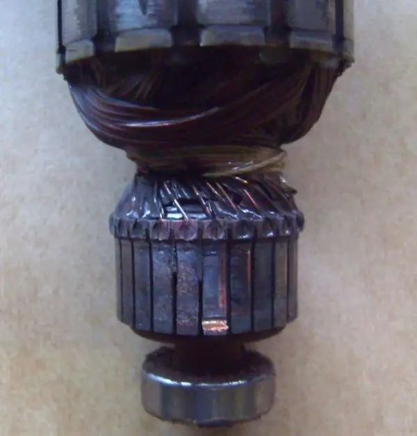
Bent manifold plates
How to check with a multimeter
-
Put a resistance of 200 ohms. Connect the test leads of the instrument to two adjacent lamellas. If the resistance is the same between all adjacent plates, then the winding is in good order. If the resistance is less than 1 ohm and very close to zero, there is a short circuit between the turns. If the resistance is two or more times higher than average, then there is a break in the winding turns. Sometimes, in the event of a break, the resistance is so great that the device goes off scale. On an analog multimeter, the arrow will go all the way to the right. And on digital it won't show anything.

Diagnostics of the winding with a multimeter Diagnostics of the armature winding with a multimeter
- The determination of the breakdown to ground is done in the absence of a winding break. Set the maximum resistance on the scale of the device. Depending on the tester, it can be from 2 MΩ to 200 MΩ. Connect one probe to the shaft, and the other to each plate in turn. In the absence of faults, the resistance should be zero. Do the same with the rotor. Connect one probe to the iron body of the rotor, and move the other along the lamellas.
Video: how the check goes
If you don't have a tester, use a 12 volt light bulb up to 40 watts.
How to check the grinder rotor with a light bulb
- Take two wires and connect them to the lamp.
- Make a break on the negative wire.
- Apply voltage to the wires. Attach the ends of the gap to the collector plates and twist it. If the light is on without changing the brightness, then there is no short circuit.
- Test for short to iron. Connect one wire to the lamellas and the other to the rotor iron. Then with the shaft. If the light is on, then there is a breakdown to ground. The winding closes to the rotor housing or shaft.
This procedure is similar to diagnostics with a multimeter.
Checking the indicator of short-circuited loops (IKZ)
There are anchors that do not have visible wires connected to the collector due to filling with an opaque compound or due to a bandage. Therefore, it is difficult to determine commutation on the collector relative to the slots. The indicator of short-circuited turns will help in this.
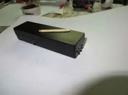
Ikz in the case
This device is small in size and easy to operate.
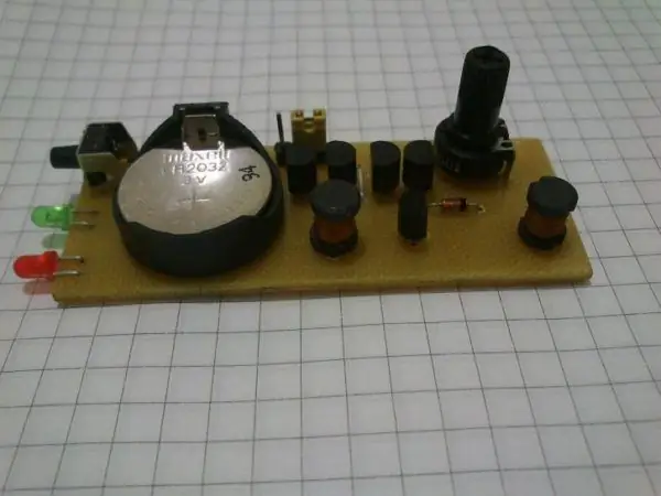
IKZ device
First check the anchor for breaks. Otherwise, the indicator will not be able to detect a short circuit. To do this, measure the resistance between two adjacent lamellas with a tester. If the resistance is at least twice the average, then there is a break. If there is no break, proceed to the next step.
The resistance regulator allows you to select the sensitivity of the device. It has two bulbs: red and green. Adjust the knob so that the red light is on. On the indicator body there are two sensors in the form of white dots, located at a distance of 3 centimeters from each other. Apply the indicator with the sensors to the winding. Rotate the anchor slowly. If the red light comes on, then there is a short circuit.
Video: IKZ at work
Diagnostics with an anchor checker (choke)
The armature checking device determines the presence of a turn-to-turn winding short circuit. The choke is a transformer that has only a primary winding and a magnetic gap cut out in the core.
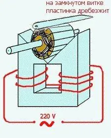
Anchor checker diagram
When we put the rotor in this gap, its winding starts to work as a secondary winding of the transformer. Turn on the appliance and place a metal plate such as a metal ruler or a hacksaw blade on the anchor. If there is a turn-to-turn closure, the plate will vibrate or magnetize to the armature body due to local oversaturation of iron. Rotate the anchor around the axis, moving the plate so that it lies on different turns. If there is no closure, then the plate will move freely along the rotor.
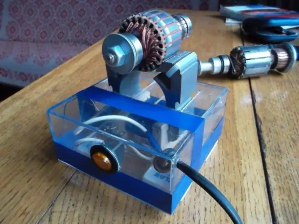
Anchor checker
Video: How to make a choke with your own hands and check the anchor
How to repair an anchor at home
Because of the anchor, a third of the breakdowns of the screwdriver occurs. With daily intensive operation, malfunctions may occur already in the first six months, for example, if the brushes are not replaced on time. With sparing use, the screwdriver will last a year or more.
The anchor can be salvaged if the balance is not disturbed. If during the operation of the device an intermittent hum is heard and there is a strong vibration, then this is a violation of balance. This anchor must be replaced. And you can repair the winding and the collector. Small short circuits are eliminated. If a significant part of the winding is damaged, it can be rewound. Grind worn out and heavily damaged lamellas, build up or solder. In addition, you should not undertake an anchor repair if you are unsure of your capabilities. Better to replace it or take it to the workshop.
Collector bore
Over time, the brush develops on the collector. To get rid of it, you must:
-
Grind the manifold using longitudinal cutters, that is, through cutters.

Straight through cutter Straight through cutter
-
We also need a reverse taper for centering on the bearing. Make a hole in it up to 8 mm.

Reverse cone Reverse cone
- Since copper is stringy, adjust the machine at 600 to 1500 rpm.
- Primary feed in half division. When the cutter slightly touches the product, make a longitudinal groove of the entire manifold. By the resulting shiny pattern, you will see the condition of the lamellas, all the unevenness of the surfaces.
- If the manifold is level, the bore will be uniform.
- If there are pits, continue grooving until the surface is flat.
- For the last pass, you need to feed the cutter one fourth of the division.
- For polishing, take a thousandth grit sandpaper and turn on the machine so that the anchor rotates in the direction that it rotates during operation.
Do not forget to clean the rotor from swarf to avoid short circuiting
Related Videos
How to rewind an anchor
Before disassembling the armature, write down or sketch the direction of the winding. It can be left or right. To determine it correctly, look at the end of the armature from the collector side. Put on gloves, use sharp wire cutters or a metal hacksaw. Remove the winding ends. The manifold needs to be cleaned and not removed. Carefully, without damaging the slot insulators, knock out the rods of the remaining parts of the winding using a hammer and a metal chisel.
Video: Remove the winding
Use a file to remove the impregnation residue without damaging the insulator film. Count the conductors in the slot. Calculate the number of turns in the section and measure the wire diameter. Draw a diagram. Cut insulation sleeves from cardboard and insert them into the grooves.
Video: Winding Left and Right
After winding, weld the leads of the sections with the collector cock. Now check the winding with a tester and short-circuit indicator. Proceed with impregnation.
Impregnation instructions (including speed controller)
- After making sure that there are no problems, send the anchor to the electric oven to warm up for better epoxy flow.
-
After warming up, place the anchor on the table at an angle for better flow through the wires. Place a drop of resin on the forehead and slowly twist the anchor. Drip until glue appears on the opposite frontal area.

Tilted impregnation Tilted impregnation
- Position the anchor horizontally and drip onto both foreheads. Twist the anchor until it loses fluidity.
-
Leave in an upright position until complete polymerization.

Air drying anchor Air dry the anchor before polymerization
At the end of the process, grind the manifold lightly. Balance the anchor with dynamic balancing and grinder. Now grind finally on the bearing. It is necessary to clean the grooves between the lamellas and polish the collector. Make a final check for open and short circuits.
Repair: Elimination of insulation breakdown
If the insulation breakdown was small and you found it, you need to clean this place from carbon deposits and check the resistance. If the value is normal, insulate the wires with asbestos. Place a drop on top with Supermoment-type quick-drying glue. It will seep through the asbestos and insulate the wire well.
If you still have not found the place of insulation breakdown, then try to carefully saturate the winding with impregnating electrical insulating varnish. Punched and non-punched insulation will be impregnated with this varnish and will become stronger. Dry the anchor in a gas oven at about 150 degrees. If this does not help, try rewinding the winding or changing the armature.
Soldering collector plates
The lamellas are installed on a plastic base. They can be erased to the very core. Only the edges remain, to which the brushes cannot reach.
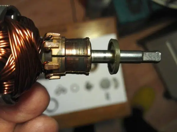
Erased slats
Such a collector can be restored by soldering.
- Cut the required number of lamellae from the copper pipe or plate to size.
- After you have stripped the anchor from copper residues, solder with ordinary tin with soldering acid.
- When all the lamellas are soldered, sand and polish. If you don't have a lathe, use a drill or screwdriver. Insert the armature shaft into the chuck. First file with a file. Then polish with zero sandpaper. Remember to clean the grooves between the lamellas and measure the resistance.
-
There are lamellas that are not completely damaged. To restore them, it is necessary to conduct more thorough preparation. Slick through the manifold to clean the plates.

Damaged manifold plate Damaged manifold plate
-
The place under the plate must be expanded with a drill carefully so as not to remove a large layer of insulator.

Expanding the place with a drill Expanding the place with a drill
- Find two pieces of copper wire, sized to fit snugly into the groove. Put the cleaned wires in the groove and irradiate.
-
Make a copper lamella blank. It should fit snugly into the groove and be higher than the existing lamellas to make soldering easier.

Lamella blank in the groove Lamella blank in the groove
-
Tape the workpiece so that there is a lot of solder. It will sit tighter in the groove. Place the workpiece in the groove and attach a soldering iron to it. Hold it until the solder melts.

Brazed blank Brazed blank
- Grind off excess with a file, grind and polish.
If the collector was completely worn out, then after soldering it will last no more than a month of active use. And not completely damaged plates after such a repair withstand several brush replacements and are not soldered out.
Galvanic extension of collector plates
Reduced copper is very hard. Collector service life as new. Galvanic build-up can restore both a completely worn out collector and partially damaged plates.
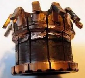
Completely worn manifold
The quality of the restoration will be the same.
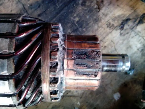
Individual plates damaged
- Clean well the entire surface of the manifold, including the insulator between the lamellas.
- Wrap bare copper wire about 0.2 millimeters in diameter.
- Wrap the anchor shaft with tape, and smear the collector from the end with plasticine so that copper does not grow where it is not needed. And so that the electrolyte does not get on the iron.
- For the tub, cut off the floor of the plastic bottle. Wrap the tape around the shaft so that it fits snugly in the neck of the bottle. Insert the anchor into the bottle.
- Take a piece of copper bus. Its size is twice the surface to be built up. Roll it up in a spiral and place it in the bottle.
-
Connect the power supply minus to the surface to be repaired, and plus to the busbar. One and a half amperes of current per square decimeter of solution. If the collector is separated from the shaft, wrap it with wire and hang it in a jar on a crossbar so that the electrolyte touches only the worn part of the lamellas. Connect bulbs of different wattage in series to regulate the amperage and prevent a short circuit on the vessel. After 24 hours, a rebuilt manifold is obtained.

Reconditioned manifold before treatment Reconditioned manifold before treatment
-
The collector must be grooved and separated by a drill or hacksaw blade. Finally, test the manifold for shorts between the plates.

Modification of the collector Modification of the collector
Electrolyte components:
- Copper sulfate - 200 g.
- Sulfuric acid 1.84 - 40 g.
- Alcohol - 5 g. It can be replaced with a triple amount of vodka.
- Boiled water - 800 ml.
How to replace an old gearbox with a new one
Grinders differ in size, power, manufacturers, but the principle of the layout of the components is the same. The new grinder engine anchor is selected strictly in accordance with the model of your tool.
-
After unscrewing all the fastening bolts of the casing, housing and gearbox, remove the gearbox with the armature from the housing. Usually the gearbox and the armature are rigidly attached to each other. To separate them, it is necessary to disassemble the gearbox.

Gearbox with anchor Gearbox with anchor
- Unscrew the mounting bolts.
- The rotor shaft is screwed to the gearbox housing with a nut. Unscrew it. Remove the gear.
- Next comes the bearing. To remove it, sometimes it is enough to knock a wooden block on the gearbox housing. But more often than not, a sticky bearing cannot be removed without some tricks. There is a plate between the impeller and the bearing, which is screwed with two screws to the gearbox. To get to them, break off a piece of a plastic impeller or use a heated nail to burn through two symmetrical holes. The second hole is needed for balancing if you are not going to change the impeller.
- Unscrew both bolts, tap with a wooden block on the gearbox housing, and the armature will detach from it. This will keep the bearing on the shaft. Remove all bearings from the shaft with a puller.
Video: how to shoot and what may be difficult
Place the new bearing in the gear housing from the rotor side. Screw on the plate that broke the impeller. Insert the gear inside the housing and thread the nut so that it fits into the grooves of the gear. Put the impeller on the new anchor, insert the anchor into the gearbox housing. Tighten the nut.
Video: Replacing the anchor
Repairing the grinder's anchor takes a lot of time. But you have a choice. You can simply change it to a new one or give it to the masters.
Recommended:
How To Make A Fence With Your Own Hands From Scrap Materials: Step-by-step Instructions For Making And Decorating From Plastic Bottles, Tires And Other Things, With Photos And Vide
How to make a hedge with your own hands. Choice of material, pros and cons. Required instructions and tools. Tips for finishing. Video and photo
Gazebo With Barbecue And Barbecue With Your Own Hands - Step By Step Instructions With Photos, Drawings And Video
Brazier, grill or barbecue: how to choose an outdoor cooking device and build a suitable gazebo for it on your site
We Repair A Coffee Grinder With Our Own Hands: How To Disassemble, Wash And Adjust, How To Grind Coffee Correctly + Video Instructions

What coffee grinders are, how to grind coffee correctly, what are the malfunctions, how to repair a coffee grinder with your own hands
Do-it-yourself Drill Repair: How To Connect A Button, Replace Brushes, Check The Rotor, Repair The Anchor, Instructions With Photos And Videos
Electric drill device. How to properly disassemble and assemble a drill. Possible malfunctions and remedies. Required tool
How To Make A Florarium For Succulents And Other Plants With Your Own Hands: Step-by-step Instructions With Photo And Video Master Classes

What is a florarium and what are its benefits? How to decorate the interior with it by doing it yourself?
