Table of contents:
- Author Bailey Albertson [email protected].
- Public 2023-12-17 12:53.
- Last modified 2025-06-01 07:32.
How to repair an electric drill with your own hands
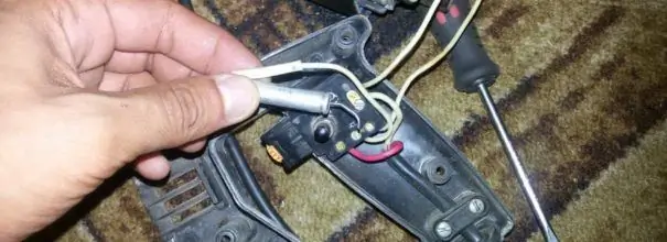
When a power tool fails, do not rush to throw it away. Having got acquainted with the device and having understood the basic mechanisms, you can independently replace the damaged assembly or part. Disassembly and assembly requires care and attention. But if this simple condition is fulfilled, you will not have to buy a new expensive tool. Knowledge is power. Extending the life of your au pair is not as difficult as it seems at first glance.
Content
-
1 Electric drill device
- 1.1 Electrical
- 1.2 Mechanical
-
2 Symptoms of electric drill problems
- 2.1 Mechanical defects
- 2.2 Signs of electrical malfunction
-
3 Do-it-yourself electric drill repair: a description of the problems and their solution
- 3.1 Required tools and materials
-
3.2 How to disassemble a drill
3.2.1 Video: how to disassemble an electric drill
- 3.3 The drill will not turn on or work
- 3.4 The drill cracks, but the chuck does not rotate
-
3.5 Power button does not work
3.5.1 Video: Replacing the Drill Button
- 3.6 Soft start does not work
- 3.7 The speed regulator does not work, its structure and replacement
-
3.8 Changing the brushes in the drill
3.8.1 Video: replacing brushes in an electric drill
- 3.9 Drill Reverse Switch Does Not Work
- 3.10 The drill rotates in one direction only
-
3.11 Replacing the bearing
3.11.1 Video: replacing the bearing in the drill
-
3.12 How to check the drill armature with a multimeter and repair it
3.12.1 Video: checking the armature of the collector motor
-
3.13 How to ring the stator of an electric drill
3.13.1 Video: how to check the armature and stator of an electric motor at home
- 3.14 The drill does not work at low speeds (the drill does not pick up speed and heats up)
-
3.15 Replacing the hammer drill
3.15.1 Video: Impact Drill Repair
Electric drill device
An electric drill consists of two interconnected parts: mechanical and electrical. It is easier to understand the structure and principle of operation if we consider these two components separately.
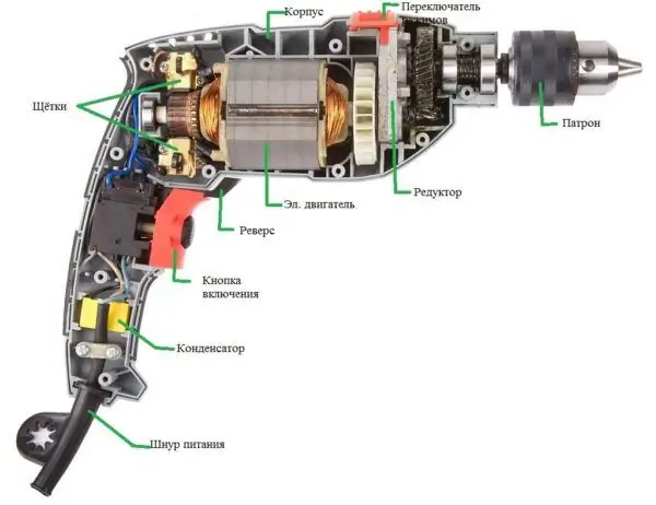
A modern electric drill consists of several units, each of which belongs to a mechanical or electrical system
Electrical part
The basis of the electric drill drive is electric current, which enters the tool from the household network through the power cord. It runs an engine (usually of a collector type) located inside the central part of the body. The electric motor consists of two elements:
- stator. It is made of high magnetic permeability electrical steel. In the technological slots windings are located - turns of copper wire, which induce a magnetic field. The stator is rigidly mounted in the tool body;
- rotor. Unlike the stator, it rotates on thrust bearings. The rotor is a working shaft on which the counter windings are located. The rotation of the armature is due to the electromagnetic interaction of the frames (windings) laid in specially machined grooves. A collector is located in the tail part of the armature, which performs the function of distributing current through the windings. Graphite brushes are directly responsible for this, to which the mains voltage is supplied. Continuous contact of the brushes with the armature collector is maintained by springs pressing on the graphite (or carbon) electrode. The rotational motion of the motor rotor is transmitted to the chuck in which the drill or other working tool is clamped.
The rotation modes are controlled by the power button located between the motor and the power cord. In the button itself (or above it) there is an adjusting wheel of revolutions and a reverse switch. For the convenience of control, a triac circuit of smooth voltage change is used in adjusting the number of rotor revolutions. Thanks to the microfilm technology, the regulator is so miniature that it can be installed in the trigger of a button.
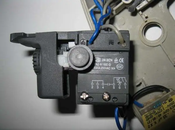
A speed regulator is built into the power button, which can be controlled using a wheel brought out to the surface
The direction of movement of the engine is switched by a reversing switch having two positions. One corresponds to clockwise movement (main mode). Another is counterclockwise movement of the shaft, which is used when loosening screws or when a drill gets jammed. The connection diagram for the reverse of the electric drill, as a rule, is shown on the mechanism itself.
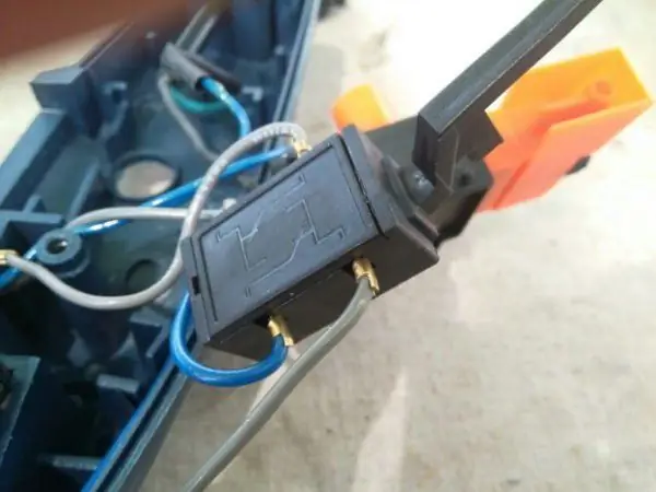
The reverse connection diagram is shown on the device body.
A capacitor is installed on the brushes in the input part of the circuit to shield the electric motor from noise in the power grid and damp back EMF (electromotive force). It is usually located on the bottom of the drill handle next to the power cord entry.
In some models, induction rings are installed to smooth out the frequency components.
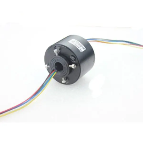
Induction ring smoothes current ripple due to the induced magnetic field
Mechanical part
The task of the electric drill is to rotate the working tool. For this, a chuck is used, which can be cam, quick-clamping or conical.
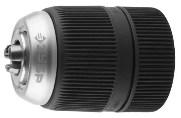
Keyless chuck allows you to change the working tool in a few seconds without the need for a key
The direct transmission of rotation from the engine to the chuck is carried out by a reducer. Its main task is to lower the speed of the electric motor, since the latter develops a speed of up to several tens of thousands of revolutions per minute. The worm-planetary mechanism copes with this. Simultaneously with a decrease in speed, an increase in the rotational power occurs. There are drills in which, along with a smooth set of revolutions, fixed speeds are added, usually two. The principle of operation of the gearshift is similar to that of a car gearbox.
In those models of electric drills that are equipped with a chiseling function, the gearbox additionally contains a ratchet mechanism. With its help, the forward and reverse movement of the cartridge is carried out, which can be considered as an impact mechanism. When the ratchet teeth jump, vibration occurs, which is used when working with concrete, brick and stone. Processing of wood and metal parts is carried out without using this mode. The ratchet is activated by a special button located on the body.
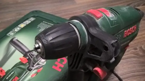
Impact mode of the drill is switched on by moving the special switch to the position indicated by the hammer
In fact, the impact system consists of two corrugated surfaces mounted on the working shaft. In normal mode, they do not participate in the drilling process, they are separated by a spring. But when, under the action of the switch, they touch and rub against each other, additional vibration occurs. At the same time, the drill must be designed for such work - usually a tool with a reinforced cutting edge, victorious soldering, etc. is used.
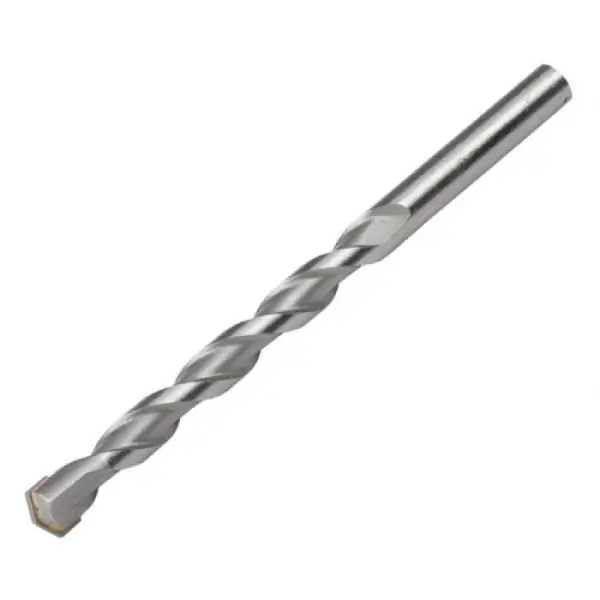
When drilling with impact, special drills with a reinforced edge are used
Electric drill malfunction symptoms
Every electric drill system can fail. It is possible to determine the causes of a malfunction by knowing their main symptoms.
Mechanical defects
The following signs indicate that the problem is with one of the mechanical devices:
- jamming of the cartridge, inability to turn it by hand;
- metal knocking and grinding during work;
- the crunch of plastic inside the case;
- hum of worn-out bearings, increased vibration;
- the impact mechanism does not turn on;
- the chuck flies off the working shaft.
Failure of the mechanics can lead to malfunctions that appear periodically. Do not hope that it will correct itself. As soon as the first signs of a problem are found, you must stop working and fix the defect. Otherwise, the cost of repairs will increase significantly.
Electrical malfunction signs
The electrical part also has its own characteristic signs of malfunction:
- the drill does not start, the motor does not rotate;
- the motor hums, but does not work;
-
brushes sparkle strongly;

Electric drill brushes The brushes are in close contact with the collector, in the event of a malfunction, they begin to spark strongly
- the speed regulator does not work, the revolutions do not change;
- the reverse does not work, the cartridge rotates only in one direction;
- the engine runs unstable, sometimes breaking down at increased speed;
- there is a characteristic smell of smoldering wiring;
- the drill body becomes hot.
DIY electric drill repair: description of problems and their solution
All malfunctions of electric drills are usually caused by improper operation, wear of individual components and mechanisms of the tool, or the use of low-quality components. To make a correct diagnosis, certain experience and electrical measuring instruments are required. Below we will look at the most common problems and how to fix them.
Required tools and materials
For self-repair of an electric drill, you must prepare:
- a set of Phillips and flat screwdrivers of various sizes and slot configurations;
- pliers, tweezers;
-
multimeter or voltage tester.

Drill Repair Tool To disassemble and assemble an electric drill, you will need a set of electrical screwdrivers
Some older models used a nut-screw connection. In this case, you will additionally need a set of keys to disassemble the drill body.
As for the replacement of parts, it must be remembered that today only the cartridge is universal for all types of drills. The rest of the spare parts are usually original. It will not be possible to rearrange them from one drill to another, unless they are of the same model. For replacement, it is necessary to purchase spare parts according to the manufacturer's catalog for the corresponding modification of the device.
Repairs are recommended to be made in a well-lit and ventilated area, the table should not be cluttered. If there is no hope for memory, you can photograph the stages of disassembly and sketch the wiring diagram. Before starting dismantling, it is imperative to disconnect the tool from the electrical network.
How to disassemble a drill
Disassembling the drill body takes a few minutes. The procedure consists in unscrewing 4-6 (depending on the model and brand) screws. After that, the body is separated into two halves, between which the engine and the rest of the device mechanisms are installed. If further disassembly is required, sequentially unscrew all the available screws and release the fasteners of the power cord, the "Start" button, the reverse switch. The motor and gearbox are removed from the housing last.
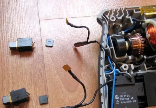
Correct disassembly begins with removing the housing cover and ends with removing the gearbox
When disassembling, it is important to remember not only the sequence of work, but also the exact location of the wires connecting the parts to each other
Video: how to disassemble an electric drill
The drill won't turn on or work
If the drill connected to the network does not work when you press the "Start" button and at the same time does not show any signs of life, you need to check the following nodes.
-
Power cord. First, the cable is visually inspected for breaks or fractures. If none are found, the second step is to check the cord with a multimeter or probe. For this, the protective casing is removed. In some models, it is not necessary to unscrew the entire cover - it is enough to remove only the plastic protection of the handle. After access to the contacts of the cord is open, the presence of voltage at the end of the wire is checked. On a working cord, the multimeter will show a voltage of 220 V. On the probe, when you touch the phase conductor, a red LED lights up.

Multimeter It is more convenient to check the integrity of the cables and the presence of voltage in certain parts of the electrical circuit with a multimeter
- If the cord is in good condition, a sequential check of the voltage on the button and the electric motor is performed.
-
Next, the operation of the capacitor and the reverse switch is checked. A defect can often be found on close inspection. The damaged part changes color or shape. For example, the plastic case of the button, inside of which the microcircuit is located, often melts during prolonged overload. When you open the casing, it immediately catches your eye. Breakdowns in the motor wiring are also visible to the naked eye - often the cause of the failure is cable breaks or an interturn short circuit. The first is accompanied by burnt terminals or contacts, breaks or sintering of conductors. The second is an unpleasant smell and blue spots on the windings. If damaged, the capacitor may deform and take a barrel-shaped shape.

Broken wiring in the electric drill Disconnecting the electrical wiring leads to the termination of the drill
The drill cracks, but the chuck does not rotate
If the tool is equipped with a hammer function, the ratchet's toothed surfaces produce a characteristic crackle when rubbed. The reason for this may be both a breakdown of the ratchet itself, and jamming of the cartridge, or rather, the shaft on which it is fixed. To fix the problem, you must disassemble the drill body to gain access to the gearbox. A careful examination will help clarify the cause of the problem and make the right decision. Often these symptoms accompany a seized bearing.
The drill, which was operated in conditions of high humidity and dustiness, must be opened from time to time and the motor and bearings must be cleaned of dust. In addition, the bearing must be lubricated after removing dust and chips. But in moderation - excess lubricant contributes to the adhesion of small debris and eventually leads to damage.

For preventive maintenance, the gearbox must be disassembled and lubricated
Power button does not work
The "Start" button controls the operation of the drill. Pulling the trigger starts the electric motor and adjusts its rotation speed. As noted above, the internal structure of the trigger button is a triac (or thyristor) circuit printed on microfilm.
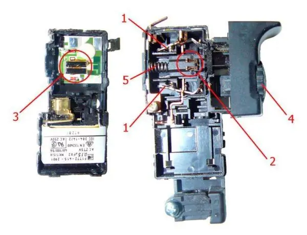
The button consists of several small parts: 1-start contacts, 2-engine speed controller, 3-electronic circuit, 4-rotation speed control wheel, 5-return spring of the button
It is impossible to disassemble and repair it at home. Therefore, if damaged, it is completely replaced. The button connection diagram is usually shown on the body as a pictogram.
If the drill circuit does not use a capacitor, only two wires from the socket and two wires from the internal circuit are connected to the button. Otherwise, separate wires from the capacitor fit to it.
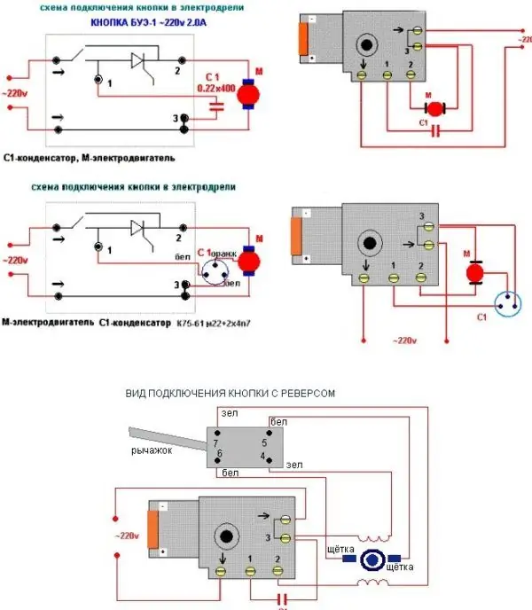
Depending on the type of electrical circuit, the button may fit from four to six wires
Video: replacing the drill button
Soft start does not work
The soft start system of the electric motor is an important component in the tool circuit. All modern drills are equipped with this feature. Thanks to it, the engine resource increases, the wear of rubbing parts in the motor is significantly reduced, and working with a drill becomes more comfortable. The main element of soft start is a triac. If it burns out, the function stops working. The best solution to the problem is considered to replace the entire button. But if this is not possible, you can replace the triac. To do this, you need to disassemble the button, remove the burnt part from the board and install a new one.
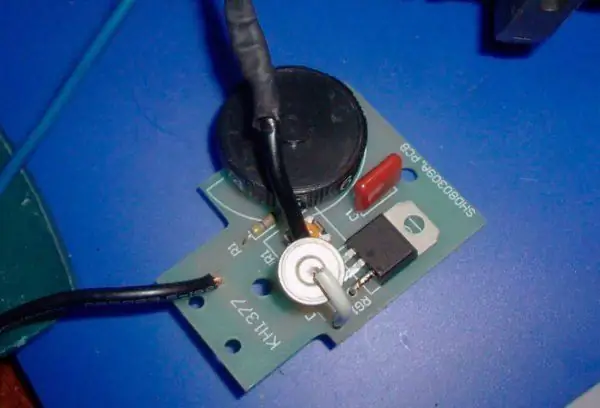
If the new button cannot be found, you can remove the board that controls the soft start function from it and replace the burnt out triac in it
Before reassembling the button, the interior is thoroughly purged and cleaned.
The speed controller does not work, its structure and replacement
In addition to the soft start system, the drill has a manual speed control system. The wheel, with the help of which the speed is changed, can be located on the button or in another place on the body. Modern models combine the soft start function and manual speed control in one electronic device, which was described above. The speed is controlled by a variable resistor.
If the speed control system is out of order and cannot be replaced, an external device can be used. For example, by including a dimmer in the power circuit break. Or assemble the device yourself from inexpensive radio components.
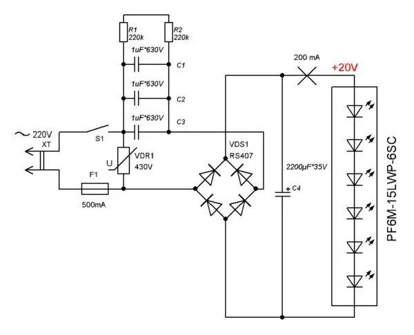
The simplest dimmer for controlling the speed of an electric drill can be assembled from inexpensive and affordable radio parts
Replacing brushes in a drill
Replacement of graphite brushes in the electric motor manifold can be planned or emergency. The first option is, of course, preferable. Operation of overly worn brushes leads to rapid wear of the collector on the rotor. Following this, the motor may burn out. The production of brushes by more than 40% is a signal for a scheduled replacement. When the serviceability threshold is reached, the brushes begin to spark, and the sparking occurs so intensely that the body heats up. You cannot bring the drill to such a state.
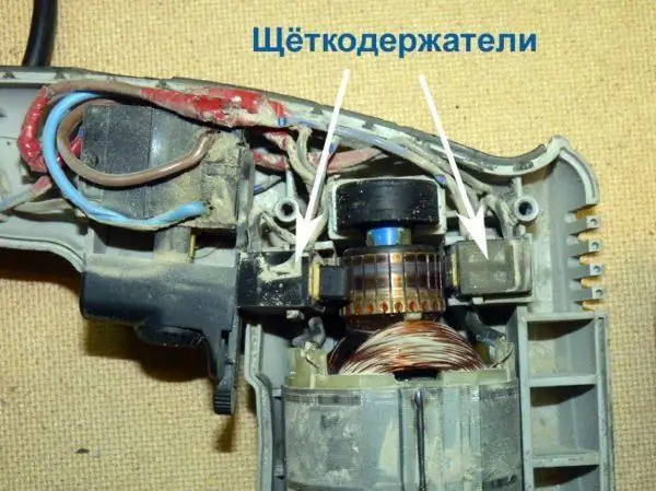
Replacing brushes, even in old models of electric drills, is quite simple: access to them appears immediately after removing the protective cover
Different models have different ways to replace the brushes. But in most modern tools, a window is left on the body through which the brushes are changed without disassembling the protective casing.
Video: replacing brushes in an electric drill
Drill reverse switch does not work
Novice users often confuse the governor and reverse drill. However, these are two different devices. And although they are located side by side, they are still enclosed in separate buildings. The principle of reverse (changing the direction of movement of the rotor) is quite simple. If you change the phase and zero on the brushes of the electric motor, the direction of rotation will change.
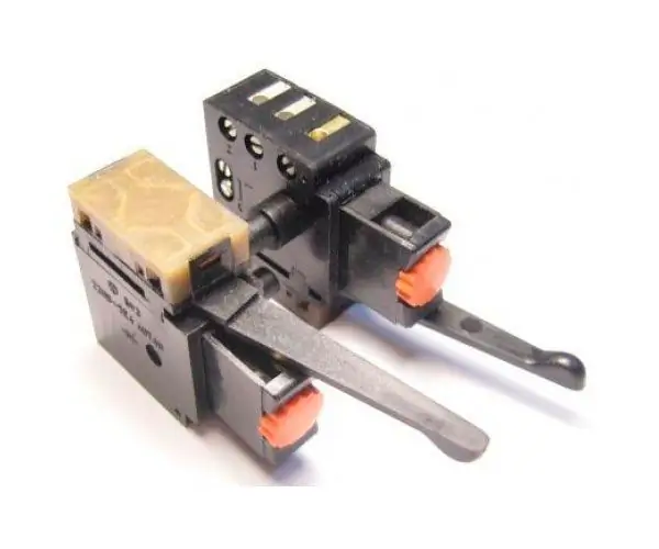
The reverse control mechanism is often located at the top of the button body
If the reverse does not work, you need to remove it from the drill and disassemble the plastic case. In fact, the device consists of a simple contact switch, so there is nothing to break there. There can be only mechanical damage in the form of a broken switch lever or burnt copper contacts. In the latter case, the terminals are stripped and the device continues to function. Damage to plastic is more difficult to fix. It's easier to buy a new part and make a replacement. The reverse connection diagram is shown, as a rule, on its body. But it is better to remember (or sketch, photograph) the original arrangement of the wires during the repair process.
The drill rotates in one direction only
Sometimes there is such a breakdown - the drill does not obey the "orders" of the reverse switch and refuses to change the direction of rotation. To restore the function of the device, you need to open the switch cover and carefully inspect the internal mechanism. If the device has two working positions, it is necessary to clean all contacts with fine emery paper and check the degree of clamping of the terminals. If the contacts are not rigid enough, bend the copper plates. Before assembling, it is recommended to clean the inside of the plastic box from dust and other possible debris.
Bearing replacement
Mechanical bearing failure is accompanied by the hum and vibration of the drill during operation. Wear occurs due to the ingress of coarse abrasive dust or chips into the protective casing, as well as due to overheating during operation and non-compliance with storage conditions. Bearings are especially sensitive to high humidity.
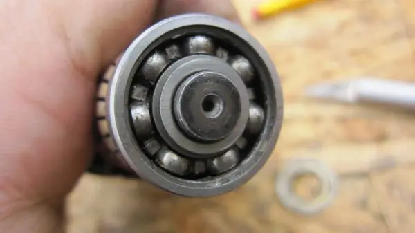
During factory assembly, the bearing is pressed onto the shaft
For replacement, you will have to completely disassemble the drill, disconnect the stator and remove the rotor on which the bearing is installed. When assembled at the factory, it is pressed onto the shaft axis. Now you need to remove it. The surest way is to use a special puller, with which the bearing comes off without distortion. You can knock it out by holding the anchor in a vice, but this must be done very carefully. Awkward movement can damage the rotor winding and then it will have to be completely changed or rewound.
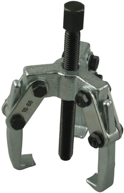
The easiest way to remove the bearing from the rotation shaft is to use a special tool.
Video: replacing a bearing in a drill
How to check the drill armature with a multimeter and repair it
If the motor hums, but the chuck does not rotate at all, or rotates very slowly, there is a good chance that the motor armature is damaged. This happens when the motor overheats, when the insulating varnish on the winding conductors melts and a turn-to-turn short circuit occurs. In order to carry out diagnostics absolutely accurately, it is necessary to disassemble the tool casing and gain access to the armature windings and the collector. The resistance of the loops in the winding is measured in series with a multimeter. To do this, the probe of the device is installed on adjacent lamellas and the ohmmeter readings are recorded. If on any pair the values deviate from the norm, then there is a short circuit.
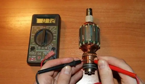
A multimeter sequentially calls out pairs of adjacent lamellas
If earlier, in the event of damage to the armature windings, the craftsmen had to rewind them on their own, today almost no one is doing this. Especially when it comes to household appliances. In the power tool market, it is quite easy and without much damage to the wallet, you can purchase a damaged part and replace it yourself. In addition, it is difficult to guarantee quality when rewinding yourself. Not everyone can withstand all the parameters. The smaller the drill, the more difficult it is to rewind the winding, since this requires special equipment.
Video: checking the armature of a collector motor
How to ring the stator of an electric drill
The stator is checked in a similar way - with a multimeter. Compared to checking the anchor, the procedure is simpler and, accordingly, faster. Indeed, there are fewer windings in the stator - usually 2 or 3 coils.
If a breakdown is detected in the coil, it is replaced. Rewinding at home is practiced only by enthusiasts of "crazy hands" and amateurs to do everything on their own. For rewinding, you need equipment in the form of a soldering iron and a template for the correct laying of the conductor.
Video: how to check the armature and stator of an electric motor at home
The drill does not work at low speeds (the drill does not pick up speed and heats up)
The engine speed depends on the device, which is discussed above, - the electric motor speed governor. If the regulator malfunctions during operation, nothing can make the engine run faster or slower. Replacing the regulator is the only correct way out of an unpleasant situation.
There are times when the speed violation occurs due to the fault of the gearbox. For example, a heavily clogged planetary gear can significantly reduce the rotational speed, especially if a large amount of oil-dried debris is “wrapped” around the axle. Broken large gear teeth and dirt in the worm gear also negatively affect rotor speed. In this case, the engine will operate in overload mode, and this is fraught with overheating and, as a result, inter-turn circuits. Therefore, a simple conclusion suggests itself. The gearbox, like all other components of the mechanism, is subject to preventive maintenance and cleaning. It is usually recommended to carry out preventive maintenance at least once every two years, and with intensive use - every year.
Replacing the hammer drill
If problems arise with the hammer mechanism of the drill, the best solution is to replace the worn ratchet gear. The ratchet mechanism is directly connected to the gearbox, so in order to gain access to it, you will have to completely disassemble the drill. No other method of restoring the ratchet has yet been invented. After replacing the gear, you should thoroughly clean the gear case from the old grease, as metal chips from the previous ratchet remained in it. New grease is added after assembly; its brand must correspond to the technical characteristics of the gearbox.
Video: hammer drill repair
When investigating the malfunctions of a drill, we must not forget that electric current is dangerous to human health. Therefore, before opening the protective cover of the tool, it is advisable to disconnect the power cord from the outlet. When checking the operation of the drill under voltage, you need to tighten the screw fastening of the case tightly. Failure to do so will result in hand and face injuries.
Recommended:
How To Check The Serviceability And Repair The Grinder Anchor With Your Own Hands, Step By Step Instructions, Video

How to check the grinder anchor for faults. DIY repair. Rotor selection and replacement
How To Replace Baking Powder For Dough In Baking: Slaked Soda And Other Options For Cake, Biscuit And Other Products + Photos And Videos

How to make lush baking can be done without baking powder at home. What to replace. Useful Tips
How To Check The Quality And Naturalness Of Milk At Home: Checking With Iodine And Other Methods, Determining The Freshness + Photos And Videos

How to determine the freshness and quality of milk at home: several proven methods. Criteria for assessing the quality of milk powder
How To Check The Freshness Of Eggs At Home And In The Store (on Water And Other Methods) + Photos And Videos

How to check the freshness of eggs before buying by external signs and at home. What can be the result of negligence? What storage conditions should be provided?
How To Connect A TV To A Computer Via WIFI: Connect And Broadcast Video With Images

How to connect a TV to a computer via Wi-Fi: connecting a TV with a smart TV function or a regular one. Instructions with illustrations and videos
