Table of contents:
- Making a jet oven with your own hands
- Description, advantages and disadvantages of the rocket furnace
- Views
- Details and operation of a reactive heat generator
- Calculation of parameters (tables)
- Construction raw materials for the construction of a custom kiln
- Preparation for the assembly of heating equipment
- Step-by-step instructions for making your own hands
- Design improvements
- Subtleties of operation of an unconventional furnace
- Author Bailey Albertson [email protected].
- Public 2023-12-17 12:53.
- Last modified 2025-06-01 07:32.
Making a jet oven with your own hands

The rocket or jet oven is the result of a deviation from the tradition of making room heating equipment. It is considered an economical heat generator, the design of which is elementary. Therefore, many are thinking about building a jet furnace with their own hands.
Content
- 1 Description, advantages and disadvantages of the rocket furnace
- 2 Types
- 3 Details and function of the reactive heat generator
- 4 Calculation of parameters (tables)
- 5 Building materials for the construction of a custom kiln
- 6 Preparation for the assembly of heating equipment
- 7 Step-by-step instructions for making your own hands
- 8 Design improvements
- 9 Subtleties of operation of an unconventional furnace
Description, advantages and disadvantages of the rocket furnace
A heat generator for heating air in a room is called a rocket oven or a jet oven, since during operation, in the event of an excessive intake of air, it emits special sounds. This noise can be mistaken for the roar of a jet engine. In normal mode, the equipment operates with a barely audible rustling sound.
The rocket stove serves as a device for home heating and cooking. It takes about 6 hours to burn one batch of firewood in such equipment, more than in a standard metal stove. The reason for this is the creation of a heat generator based on an overhead combustion furnace.

The flame from the jet furnace may burst
The advantages of the rocket furnace include:
- independence from fuel energy;
- simplicity of design, consisting of available parts, connected in a matter of minutes;
- the ability to provide a lot of heat, despite the quality of the loaded fuel.
The jet furnace also has some disadvantages:
- manual control, which implies constant monitoring of equipment operation;
- danger of getting burned, because the walls of the equipment become extremely hot;
- inappropriateness of use in a bath, since it will not be possible to warm it up.
Views
A unit that emits a rocket hum during operation is:
-
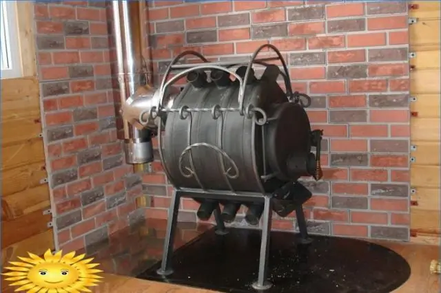
portable (a unit made of metal pipes, buckets or a gas cylinder);

Portable version of the jet furnace Portable rocket furnaces are mass-produced by the industry
-
stationary (made of fireclay bricks and metal containers);

Reactive brick oven Such a unit is more difficult to build than a metal oven.
-
equipment for heating air with a couch.

Reactive stove with resting place The bed is equipped behind the rear wall of the oven
Portable structures are made in large batches, because they are used for hiking. The basis of these heat generators is a pipe made up of several sections. True, such designs, unlike units based on fireclay bricks, are not reliable. The walls of the refractory blocks increase the heat transfer of the jet furnace. If desired, you can add a couch or bed decorated with clay or sawdust to it.
Details and operation of a reactive heat generator
An elementary rocket furnace is a device of two pieces of pipe connected by a 90-degree bend. The combustion chamber in this heat generator is usually a zone in the horizontal part of the structure. But sometimes the fuel is put into the vertical section of the apparatus, for which the rocket furnace is constructed from two pipes of different lengths, mounted vertically and connected by a common horizontal channel.

Primary and secondary air flows through the furnace
The operation of a jet furnace is based on two actions: the unimpeded passage of wood gases through the pipe and the afterburning of gases generated during the combustion of fuel. Chips and firewood are placed in the firebox of this heat generator after a highly flammable material like paper has ignited there. A container with water or other contents is placed on the open section of the pipe. At the same time, a small space is left between the structure and the installed container, which is necessary to create traction.

The processes taking place inside a stationary jet furnace resemble the work of pyrolysis heating units
Calculation of parameters (tables)
The volume of the furnace should be determined with knowledge of the matter, because it is he who affects the power and amount of heat generated by heating equipment. When calculating the dimensions of the jet heating equipment, use the indicator of the inner diameter of the drum D, the value of which can fluctuate within 300-600 mm. You also need to know the cross-sectional area of the drum. To determine this indicator of the rocket furnace, you should use the formula: S = 3.14 * D ^ 2/4.
The main dimensions of the jet furnace are shown in the table:
| Parameter | Value |
| Drum height H | 1.5D to 2D |
| Height of the heat-insulating coating of the drum | 2 / 3H |
| Drum insulation thickness | 1 / 3D |
| Cross-sectional area of the primary flue | From 0.045S to 0.065S (optimal - from 0.05S to 0.06S). The higher the primary chimney, the better. |
| Minimum clearance between the top edge of the primary flue and the drum cover | 70 mm. At a lower value, the aerodynamic resistance of the gap for gases passing through it will be excessively large. |
| Flame tube length and area | Length and area of the primary chimney |
| Blower sectional area | Half the cross-sectional area of the primary chimney |
| Cross-sectional area of the external chimney | 1.5S to 2S |
| The thickness of the adobe cushion under the flue with a stove bench | 50-70 mm (if there are wooden planks under the bench - from 25 to 35 mm) |
| The height of the coating above the gas duct with a stove bench | 150 mm. It is not recommended to reduce it, otherwise the stove will accumulate less heat. |
| External chimney height | not less than 4 m |
Particular importance is attached to the length of the flue with the stove bench. The maximum permissible indicators are shown in the table:
| D (diameter) | Length |
| 300 mm | 4 m |
| 600 mm | 6 m |
The volume of the secondary ash chamber is also an important indicator, depending on the volume of the drum and the primary chimney.
| D (diameter) | Volume | |
| 300 mm | 0.1x (Vk - Vpd) | Where Vk is the volume of the drum, Vpd is the volume of the primary chimney. |
| 600 mm | 0.05x (Vk - Vpd) | |
Construction raw materials for the construction of a custom kiln
The production of jet heating equipment will require:
- barrels with a volume of 200 liters and a diameter of 0.6 meters, an empty bottle of liquefied gas or tin buckets to build a furnace drum;
- square or round pipes made of steel with a thickness of 2-3 mm, which are needed to create a blower, combustion chamber and primary chimney;
- fireclay crushed stone and kiln clay as thermal insulation materials;
- adobe, which serves as an outer coating layer;
- fireclay bricks;
- sand from the bottom of the river;
- cuts of zinc-coated steel or aluminum sheets for the manufacture of covers and doors;
- asbestos or basalt cardboard, performing the tasks of a compactor.
Of the tools for the construction of a rocket furnace, you will need a welding machine. And if you plan to make heating equipment out of bricks, then you will have to take:
- Master OK;
- mortar blade;
- hammer pick;
- jointing;
- acute-angled sledgehammer;
- level;
- plumb line;
- roulette.
Preparation for the assembly of heating equipment
When choosing a place for a rocket stove, they are guided by some rules:
- reactive heating equipment is placed only in a room with an area of at least 16 m²;
- installation of equipment will be easier without floorboards under the oven;
- it is forbidden to place wood beams over a structure that gives heat;
- if it is assumed that the chimney will go through the ceiling, then the heating equipment is placed in the middle of the house;
- the heat generator cannot be installed near the outer contour of the house, otherwise the room will lose heated air;
- the jet device must not be located near walls and partitions of their wooden materials.
To make it convenient to put fuel into the jet heating equipment, it is more reasonable to put it with its front side opposite the entrance. It is important to leave at least a meter of unoccupied area around the rocket furnace.
In a small house, builders are advised to set aside a place for the stove in the corner. In this case, the firebox should be directed in one direction, and the stove bench (if made) - in the other.

The oven stands on a special platform that protects the floor from high temperatures
Having found a suitable site for a rocket furnace, they begin to prepare it for construction work. If boards are laid on the floor in the house, then in the place where the equipment will be installed, they will need to be removed. A hole is being dug under the exposed floor, the bottom of which is necessarily pressed.
A special solution should be mixed before construction work. It consists of sand and clay, combined in a 1: 1 ratio. So much water will be required for the construction raw materials to acquire the consistency of sour cream, that is, ¼ part of the amount of dry ingredients.
Step-by-step instructions for making your own hands
If it is planned to make a rocket furnace from a gas cylinder, then you can not be afraid of difficulties. The steps to create equipment from such construction materials are quite simple:
-
the upper part is cut off from a cylinder with a volume of 50 liters in order to build a kind of cap;

Blank part for rocket furnace The balloon is cut from the top and bottom
-
focusing on the instructions in the drawing, all parts of the product are welded to each other, that is, a gas cylinder, a pipe with a diameter of 10 cm (future chimney), a pipe with a diameter of 7 cm (internal channel) and another pipe with a diameter of 15 cm (firebox);

Drawing of a rocket furnace from a cylinder with a secondary air supply Dimensions are in mm
- the space between the two pipes is filled with a material that retains heat, for example, sand, which has been thoroughly calcined, that is, cleaned of organic matter;
- to give the structure stability, the legs are welded.
To build a rocket furnace with a stove bench, which implies the use of bricks, you need to act differently:
-
The zone for arranging the firebox is deepened by removing 10 cm of soil. The combustion chamber is formed from fireclay bricks. Formwork is created along the contour of the structure being manufactured. To make the base strong, it is recommended to lay reinforcement mesh or metal rods in it;

Pouring the foundation of the rocket furnace The platform will harden in about two days
- The structure is poured with liquid concrete. Then they wait for the solution to harden and finish the work. The bricks are laid in a solid line, creating a platform for the oven. After that, the walls of the structure are formed, exposing several rows of brick blocks;
-
The lower channel of the structure is equipped, while one line of bricks is laid across to block the combustion chamber. The blocks are placed, leaving the vertical channel and the opening of the firebox open;

DIY combustion chamber The two sectors of the furnace at this stage of construction must be open
-
They find a body from an old boiler and cut off the top and bottom covers on it. At the bottom of the resulting pipe, a flange is installed through which a horizontal heat exchanger will pass. Parts are required to be connected to each other with a continuous weld;

Installation of the lower branch pipe Work requires accuracy
- An outlet pipe is inserted into the barrel, after which a brush is taken for metal and rust is scraped off the walls of the container. The cleaned barrel is treated with a primer, and a little later with paint that is resistant to high temperatures;
- The horizontal chimney is welded to a side outlet - the future ash pan. To facilitate its cleaning, a sealed flange is mounted;
-
The fire tube is laid out from refractory bricks. At the same time, a channel with a height and width of 18 cm is formed inside the structure. When doing this, they constantly use the building level, which allows you to control the verticality of the product;

Fire tube laying Pipe height is determined in advance
- The flame tube is covered with a protective casing, and the resulting gaps are sealed with perlite. The lower area of the vertical channel is sealed with wet clay, the function of which is to prevent the insulation material from spilling onto the floor;
- A fuel tank is formed from the boiler, on which the top and bottom have been cut. A handle must be welded to it;
-
To improve the look, the structure is treated with adobe putty, consisting of sawdust and raw clay. The first component of the composition serves the same as crushed stone in concrete, that is, it prevents cracking of the furnace walls. It is recommended to apply adobe putty over the perlite backfill;

Furnace body coating The special composition is recommended to be sculpted with gloves
- The facade of the furnace is created, for which the furnace contour is laid out of stone, bricks, adobe and sand. The seamy side of the structure is filled with crushed stone, and the front side is filled with an adobe mixture, which makes the surface perfectly flat;
- A metal barrel casing is placed on the previously created base. The lower branch pipe of the container is directed towards the bed. The bottom of the structure is treated with raw clay, which will ensure its tightness;
-
A channel from a corrugated pipe is brought to the combustion chamber. It will serve as a link between the firebox and the outside atmosphere;

Making a channel through which air will flow At this stage, the oven looks almost finished.
- Carry out a test kindling of the furnace, watching how the gases are removed from the horizontal chimney. After that, the pipes of the heat exchanger are connected to the lower branch pipe installed on a red brick platform;
- The stove is supplemented with a smoke exhaust pipe. The junction of the chimney and the heat generator is sealed with a refractory coating and an asbestos cord;
-
Using clay and adobe, the couch is given the desired shape. Only the horizontal section of the structure is left unsealed, which will then be used during cooking.

Scheme of a jet furnace with a stove bench The oven functions as a whole system
Design improvements
A bed with a gas flue inside is not the only option for modernizing the rocket furnace. The design can be improved with a water jacket connected to a heating system in which water is circulated. It is desirable to give this part of the structure the appearance of a coil created from a copper pipe twisting on a chimney.

This design gives even more warmth
Another way to improve the reactive furnace is associated with the organization of the flow of heated secondary air into the fire tube. This will increase the efficiency of the heat generator, but will lead to the deposition of a large amount of soot in the primary chimney. Therefore, it is best to make sure that the drum cover can be removed if necessary.
Subtleties of operation of an unconventional furnace
The rocket furnace is stoked by analogy with the upper combustion heat generator. It turns out that the kindling of equipment called a rocket should be carried out according to certain rules:
- the main raw material for the furnace of the unit should be laid only after good heating of the structure, for which first sawdust or paper is placed in the blowing sector and set on fire;
- they must react to muffling the hum emanating from the furnace - they put a large batch of fuel into the combustion chamber, which will ignite on its own from the red-hot remains of sawdust;
- the process is closely monitored, that is, after laying the firewood, the damper is fully opened, and after a while, when the equipment makes a hum, it is covered to obtain a sound similar to rustling;
- as necessary, the damper is covered more and more, otherwise the firebox will fill with an excess volume of air, which will disrupt pyrolysis inside the flame tube and lead to the creation of a strong hum.
Since the jet furnace was originally designed for use in the field, its design is extremely simple. This allows an ordinary home craftsman to cope with the manufacture of the unit. But, despite the apparent lightness, the rocket furnace is supposed to be assembled, taking into account the correct ratio of parameters. Otherwise, the equipment will turn out to be unproductive.
Recommended:
Making A Buleryan (breneran) Stove With Your Own Hands: Advantages And Disadvantages Of The Design, A Device With Drawings, Instructions With A Video, Etc

Design and principle of operation of the "Buleryan" furnace (breran). DIY recommendations with instructions and drawings. Maintenance and operation
How To Make A Long Burning Stove With Your Own Hands: Manufacturing Instructions With A Diagram And Drawings + Video

How to make a long burning stove with your own hands. Consumables, recommendations, diagrams, design features
Long-term Burning Stove (including Sawdust And Wood) With Your Own Hands: Diagram, Drawings, Etc. + Video

How does a long burning stove work. Production of a long-burning furnace from a gas cylinder and sheet metal. Features of operation and repair of furnaces
How To Make A Comfortable Computer Desk With Your Own Hands: Drawings, Diagram, Detailed Instructions + Video

Practical advice and recommendations for making a computer desk. Required materials and tools, step by step instructions
How To Install Polypropylene Pipes With Your Own Hands: Installation, Instructions, Diagram, Recommendations + Video

Practical recommendations for installing polypropylene pipes with your own hands. The use of polypropylene pipes for water supply and sewerage systems
