Table of contents:
- Author Bailey Albertson [email protected].
- Public 2024-01-17 22:26.
- Last modified 2025-06-01 07:32.
How to mark, install and connect sockets in the kitchen

The socket in the home is an important infrastructure element that provides electricity to various appliances. When carrying out a major overhaul in the kitchen, you have to deal with a complete rework of the entire power supply circuit. At first glance, the procedure may seem complicated, but if you understand in detail what is what and draw up a detailed plan, the installation will be much easier.
Content
-
1 Types and characteristics of sockets
- 1.1 Photo gallery: types of sockets
- 1.2 Standards for the installation of sockets in the kitchen
-
2 Drawing up the layout of the sockets
- 2.1 Determining the required number of outlets
- 2.2 Location of outlets for each type of household appliance
-
2.3 Wiring rules
2.3.1 Table: power and cross-section of wires for connecting kitchen appliances
-
3 Preparing to install outlets
- 3.1 Required tools
- 3.2 Safety precautions
-
4 Instructions for installing and connecting sockets in the kitchen
-
4.1 Measurements and marking of socket locations
4.1.1 Video: marking holes for socket boxes
-
4.2 Making holes for rosettes
4.2.1 Photo Gallery: Wall Drill Bits
-
4.3 Creation of grooves in the walls for laying wires
- 4.3.1 Standards and requirements for the chasing process
- 4.3.2 Chipping tools
- 4.3.3 Wall chipping
- 4.3.4 Video: cutting walls with a wall chaser
- 4.4 Connecting and fixing the power lines to the socket
-
4.5 Fixing the socket in the wall
4.5.1 Video: installation of socket boxes
- 4.6 Mounting the socket
-
4.7 Checking the functionality of the socket
4.7.1 Video: how to measure the voltage in the network
-
Types and characteristics of sockets
Electrical outlets are divided into the following types:
- by type of installation - internal and overhead. The former are used for hidden wiring, the latter for surface wiring, for example, in wooden houses;
- with protective curtains. These sockets are protected by the holes into which the plug is inserted. The curtains are moved back only at the moment of its installation;
- with ejectors. They are used in the event that you often have to turn on and off the plugs to change devices;
- with a timer. With the help of such a device, you can set a program for turning on / off the power of one or another consumer;
- with a switch. Allows you to turn off the power so that the plugs of the devices are not removed when not in use.
Photo gallery: types of sockets
-

Internal socket -
Internal sockets are designed for hidden wiring and look more attractive than overhead
-

Overhead socket - Surface-mounted sockets are used for surface wiring
-

Socket with switch - Sockets with a switch allow you to turn off the power without removing the plug of the electrical appliance
-

Pusher socket - Ejector sockets are convenient in situations where the plug of an electrical appliance has to be inserted / removed frequently
-

Timer socket - Equipping the outlet with a timer allows you to turn on and off the electrical appliance at a specified time
-

Curtain socket -
The presence of shutters in the outlet provides protection for the holes
With regard to the technical characteristics of the sockets, the main parameters are voltage, current and frequency. In accordance with European standards, the voltage in the network is 220-240 V or 380 V. 220 V sockets are used, as a rule, to connect consumers with a capacity of up to 3.5 kW. This limitation is explained by the fact that standard sockets, which are designed to work with low-power equipment, are unable to withstand a current exceeding 16 A. If there is a need to connect devices of higher power, three-phase devices should be used that are designed for a current of 32 A and a voltage of 380 V. For this, a certain frequency of current in the mains is provided for different outlets, usually 50 or 60 Hz. In Russia, the European frequency standard of 50 Hz is used.
Standards for installing sockets in the kitchen
Before proceeding with the installation of outlets in the kitchen, you must familiarize yourself with the standards for the installation of these elements, their types and wiring rules. The main provisions of the normative documents governing the arrangement of the sockets are as follows:
- height - no more than 2 m from the plinth, depending on the specific consumer;
- a household appliance connected to an outlet must be located at a distance of no more than 1 m from it;
-
the risk of splashing water or steam must be completely excluded.

The location of the sockets in the kitchen The installation locations of the sockets in the kitchen must be selected so as to completely eliminate the risk of splashing water and steam on them
Drawing up a layout of outlets
When planning a major overhaul of the kitchen, you need to take care of drawing up a plan for the location of the outlets in order to avoid unnecessary hanging wires, as well as inconvenience when connecting electrical appliances.
Determining the required number of outlets
To determine the number of outlets in the kitchen, it is necessary to add up all the household appliances that are planned to be used, and add another 20% as a reserve. The most common kitchen consumers are:
- hoods;
- plates;
- fridge;
- built-in appliances;
- kettle, mixer, etc.
To the resulting list, it is also worth adding devices that may be used in the future. All calculations should be performed at the wiring stage, that is, before the start of finishing work, since it will not be easy to install additional sockets later.

The number of sockets at each connection point in the kitchen directly depends on the number of electrical appliances that will be used in the immediate vicinity of it
The location of the sockets for each type of household appliances
Depending on the consumer, the socket should be located at a certain level from the floor:
- Plate. The basic rule is that sockets should not be placed over the burners or behind the oven. The optimal distance from the floor is 15 cm with some indentation to the side, so that the plug is accessible, but the outlet is not in sight.
- Fridge. The recommendations are generally identical. Plus, it should be borne in mind that some models of refrigerators have a short power cord, which will not allow the outlet to be located far.
- Washing machine and dishwasher. A similar technique has openings on the back for the supply and drainage of water, so the outlet should be located at some distance. It is better to place it on the opposite side of the hoses at a height of 15-20 cm from the floor.
- Hood. Since this device is installed quite high, the socket should also be located closer to the ceiling, as a rule, 2 m from the floor.
-
On the apron. Typically, this area is a work area for cooking, so connecting kitchen appliances may be required quite often. So that the plug can be turned on and off without difficulty, the socket is placed 10-15 cm from the edge of the table top or 110-115 cm from the floor. It is not worth placing it too high, since the apron is a noticeable place in the kitchen and the wires that are in plain sight will only spoil the interior.

Typical layout of outlets in the kitchen Depending on the type of appliances to be connected, sockets in the kitchen should be located at a certain height from the floor
In the area of the kitchen where the sofa, table and chairs are installed, the presence of an outlet is also extremely important, for example, for connecting a vacuum cleaner, charging for a phone or laptop. In this case, it is better to put a pair of double sockets at a height of 20-30 cm from the floor. A higher position will show the wires.
Layout rules
Connecting sockets in the kitchen is performed according to the following rules:
- The total power of consumers that are connected to the outlet should not exceed the maximum allowable.
- When operating equipment with high power, it is necessary to bring a dedicated line to it and install a separate machine.
- If there are electrical appliances with a metal housing, they must be grounded.
- It is not recommended to install outlets behind electrical equipment that generates heat (ovens, refrigerators, etc.).
-
Before starting the installation, a plan should be drawn up.

Wiring lines For each group of outlets, designed to consume significant power, it is better to make a separate line
Table: power and cross-section of wires for connecting kitchen appliances
| Types of equipment | Maximum power consumption | Power socket | Cross section cable | Machine in the dashboard | |
| Single phase connection | Three-phase connection | ||||
| Dependent set: electric panel plus oven | about 11 kW | Designed for the power consumption of the kit |
Up to 8.3 kW / 4 mm² (PVA 3 * 4) 8.3-11 kW / 6 mm² (PVA 3 * 6) |
Up to 9 kW / 2.5 mm² (PVA 3 * 2.5) 9-15 / 4 mm² (PVA 3 * 4) |
separate, not less than 25 A (only 380 V) plus RCD |
| Electrical panel (independent) | 6-11 kW | Designed for panel power consumption |
Up to 8.3 kW / 4 mm² (PVA 3 * 4) 8.3-11 kW / 6 mm² (PVA 3 * 6) |
Up to 9 kW / 2.5 mm² (PVA 3 * 2.5) 9-15 / 4 mm² (PVA 3 * 4) |
separate, not less than 25 A plus RCD |
| Electric oven (independent) | 3.5-6 kW | euro socket |
Up to 4 kW / 2.5 mm² (PVA 3 * 2.5) from 4 to 6 kW / 4 mm² (PVA 3 * 4) |
16 A 25 A |
|
| Gas panel | euro socket | 1.5 mm² (PVA 3 * 1.5) | 16A | ||
| Gas oven | euro socket | 1.5 mm² (PVA 3 * 1.5) | 16A | ||
| Washer |
2.5 kW 7 kW with drying |
euro socket |
2.5 mm² (PVA 3 * 2.5) 7 kW / 4 mm² (PVA 3 * 4) |
separate, 16 A separate, 32 A |
|
| Dishwasher | 2-2.5 kW | euro socket | 2.5 mm² (PVA 3 * 2.5) | separate, 16 A | |
| Refrigerator, freezer | less than 1 kW | euro socket | 1.5 mm² (PVA 3 * 1.5) | 16 A | |
| Hood | less than 1 kW | euro socket | 1.5 mm² (PVA 3 * 1.5) | 16 A | |
| Coffee machine, double boiler, microwave oven | up to 2 kW | euro socket | 1.5 mm² (PVA 3 * 1.5) | 16 A | |
Preparing to install outlets
Any construction or repair work begins with preparation, and the installation of outlets is no exception. For work, you will need to prepare the appropriate tool and familiarize yourself with safety precautions.
Required tools
The set of tools and materials may differ depending on which wall the sockets are supposed to be installed in (concrete, drywall, etc.). In most cases, the following list is required:
- grinder or wall cutter;
- perforator for drilling nests;
- crown for working with wall material;
- knife, nippers, screwdriver;
- putty knife;
- roulette;
- gypsum and alabaster;
- deep penetration primer;
- socket box;
- wires;
-
pencil.

Socket Mounting Tools To mount the sockets, you will need a fairly large list of tools, ranging from screwdrivers to a puncher
Safety engineering
Any work related to the installation of electrical fittings must be carried out in accordance with the safety rules:
- Electrical work must be carried out in a room with a de-energized network.
- Each wire used for connection must be checked with an indicator screwdriver or a phase indicator.
- Installation should be carried out with a tool with rubberized handles.
- To lengthen the wire, the connection points should be soldered or connected with special elements, and not twisted.
- When installing the socket, it is considered unacceptable to contact the body with bare wires.
- When installing the socket into the wall, you need to control the reliability of its fastening and insulation.
- If the length of the wire turns out to be longer than necessary, the excess part is cut off or laid in the wall.
- For installation it is necessary to use only those equipment and wires that are designed for work with electricity and are designed for the rated power and current.
Instructions for installing and connecting sockets in the kitchen
Installation of sockets consists of a number of operations that are performed in a specific sequence.
Measurements and marking of locations of outlets
Regardless of whether the wiring has already been completed or the walls will be grooved at the same time as drilling the holes for the sockets, the installation of the socket boxes begins with measurements and marking on the wall.
To make marks for future sockets, you need to accurately determine their location, which is far from always possible. Plus, it is worth considering the likelihood of rearrangement. Therefore, it is best to carry out the markup, adhering to the following rules:
- for large equipment 1 m recede from the floor;
- over bedside tables and countertops make an indent 10 cm from the surface;
- for universal use, the markings are made at a height of 30 cm from the final finish of the floor;
- the distance between the centers of the sockets (when installing the socket strip) is unchanged and is 71 mm, provided that the socket boxes of standard sizes are installed;
- the minimum distance from door frames, ceiling, as well as corners and floor should be 15 cm;
- the sockets must be at least 50 cm away from radiators.
The actual markup is quite simple:
- Applying the level to the wall, draw a horizontal line with a pencil at the required height.
- Draw a point that corresponds to the center of the future hole.
-
Using a level, draw a vertical line on the point.

Layout of socket boxes To make a hole for the wall sockets, you first need to apply the markings
Video: marking holes for socket boxes
Making holes for rosettes
For a standard size socket, which has a diameter of 64 mm and a depth of 40 mm, crowns with a diameter of 68 mm and a length of the working part of 60 mm are used. The gap, which forms between the box and the edge of the hole in the wall, ensures a secure fixing of the socket using a plaster mix. It is worth taking into account that the holes for the boxes are drilled in a shockless mode. Otherwise, the equipment may be damaged.
Depending on the material in which you want to drill the hole, the choice of both the crown and the power tool itself will differ. For soft materials, an electric drill will be enough, but for hard materials it is advisable to use a 1.5 kW perforator.
Photo gallery: wall drill bits
-

Wood crown set - Wood crowns have a peculiar design and are usually sold as a set for drilling holes of different diameters.
-

Drywall crowns - The crown (cutter) for drywall is a cutting edge with sharp teeth
-

Concrete crown - Carbide tipped bits are used for concrete or brick
After preparing the necessary tool, you can start drilling the holes for the boxes:
-
Clamping the crown in the chuck of the drill (punch), we point the drill to the intended point.

Installing the crown We clamp the crown in the chuck of the power tool and point it to the intended point
-
We turn on the instrument and begin to dive to the required depth.

Hole drilling We plunge into the wall with a crown to the desired depth
-
When the cut is complete, gouge out the rest of the concrete with a hammer and chisel.

Removing concrete residues After drilling, it is necessary to remove the remaining concrete from the hole
When drilling holes, it is recommended that you stop the power tool and remove the core bit from the wall to cool down. In addition, you can periodically spray water on the wall. This will exclude not only overheating of the nozzle, but also reduce the amount of dust.
Creation of grooves in the walls for laying wires
To start chipping the walls, you need to draw up a wiring drawing and prepare the appropriate tool.
Standards and requirements for the chasing process
The wiring drawing is made in accordance with building codes, which are regulated by SNiP 3.05.06-85. The diagram shows not only lighting fixtures, sockets and switches, but also the route for laying wires. Slitting is performed taking into account the following requirements:
- the depth of the furrow should be no more than 2.5 cm, width - 3 cm;
- the maximum distance for one channel from the junction box to the outlet or other electrical fittings is 3 m;
- cable and grooves lead only horizontally or vertically using a level. You cannot use diagonal lines or wavy lines;
- the minimum distance from floor slabs to horizontally located strobes is 15 cm, from gas and heating mains - 40 cm;
- the vertical slot must run at least 10 cm from the door frame and window opening;
-
When planning your wiring, bends should be minimized from junction boxes to outlets and other points.

Location of strobes Cable grooves are made only vertically or horizontally
It is prohibited to perform chamfering in corners, bearing walls and floor slabs, since slots can reduce the strength of the structure of the building and lead to unpredictable consequences
Chipping tools
The following tools can be used to make channels for wiring in the wall:
- hammer and chisel - the primitive and most time consuming method that can be used to make a small length of strobe;
- perforator with a special nozzle - allows you to get a result of average quality, since the edges of the slots are uneven, chipped and require additional processing;
- a grinder with a diamond disc - allows you to perform a high-quality strobe, but the disadvantage of this option is the formation of a large amount of dust;
-
The wall chaser is a professional tool used by builders.

Hammer and chisel A hammer and a chisel or a bolt is the simplest and most affordable tool that you can use to gouge walls
Wall slitting
When using a wall chaser, the slots are performed as follows:
- We take the typewriter and apply the edge to the wall that is closer to the dust outlet.
-
We deepen the power tool and carry it to the desired distance.

Wall chamfering with a wall chaser We deepen the wall chaser into the wall and carry it to the desired distance along the marked line
-
After the strips are cut, use a chisel or chisel to knock out pieces of wall material.

Removing excess material Chisel and hammer remove pieces of wall material from the slot
- We clean the grooves of dust and prime them, after which you can lay the wires.
Video: cutting walls with a wall chaser
If a puncher is used instead of a wall chaser, then the technology is slightly different:
-
Along the entire length of the marking with an interval of 10-15 cm, we make holes with a drill at a right angle in accordance with the depth of the groove.

Drilling a wall Holes are drilled along the marked line with a puncher
-
We select the material between the holes with a perforator with a special nozzle, holding it at an angle of 45˚.

Punching a groove with a perforator A perforator with a special nozzle at an angle selects a slot of the desired depth
- We align the edges of the resulting slot with a semicircular chisel.
Connecting and fixing the power lines to the socket
We install the electrical wiring as follows:
- We remove dust from the slots with a vacuum cleaner and treat them with a primer.
-
We open the cover of the junction box and put a wire into it.

Junction box The new cable, which is routed to the outlet, is inserted into the junction box
- We lay the cable in the groove (it is recommended to first pass it through the corrugation), while it should be located freely.
-
We fix the wire in the recess with plaster solution or special clips with a step of 25 cm.

Wire fixation In the groove, the wire is fixed using special clips or a plaster mixture
- We bring the wire to the installation site of the socket and cut it off with a margin of 15-20 cm.
-
We seal the cable with a gypsum mixture or plaster based on cement and sand.

Wire termination The wire in the groove is sealed with plaster
Fixing the socket in the wall
The installation of the socket outlets in the wall is carried out in the following order:
-
We try on the box to the hole, while nothing should interfere with its landing.

Fitting a socket The box must be tried on before installation
-
We clean the hole from dust, prime it and let the composition dry.

Hole cleaning The hole must be cleaned of dust and primed
- We remove a piece of plastic in the socket, through which the wire will be wound.
-
We dilute the plaster mix and apply it to the bottom and walls of the hole, as well as to the outside of the box.

Mixture application The plaster mix is applied to the bottom and walls of the hole
-
We pass the wire into the socket box and install the latter into the solution, aligning the upper edge with the wall.

Box installation After applying the mixture, the box is mounted flush with the wall
-
Using a level, we check the horizontalness of the mounting lugs.

Checking the horizontal position of the socket box Level check the horizontal installation of the socket boxes
-
We cover up the cracks between the wall and the socket, remove the solution that got inside the box.

Sealing cracks We close up the cracks between the box and the wall and remove the solution that got inside
Video: installing socket boxes
Mounting the socket
To attach the socket, you will need a Phillips and flathead screwdriver, as well as side cutters.
Installation is performed in the following sequence:
-
With side cutters or a knife, we strip the ends of the wires from the insulation, stepping back from the edge of 10 mm.

Wire stripping We clean the ends of the wires with a knife or side cutters
-
In the junction box, we interconnect a new cable and a wire from which power is supplied, using special connectors or a galvanized bolt with a nut and washers.

Wire connection In the junction box, we connect the new cable to the incoming wire - phase to phase, zero to zero
- We remove the decorative overlay from the outlet along with the frame.
-
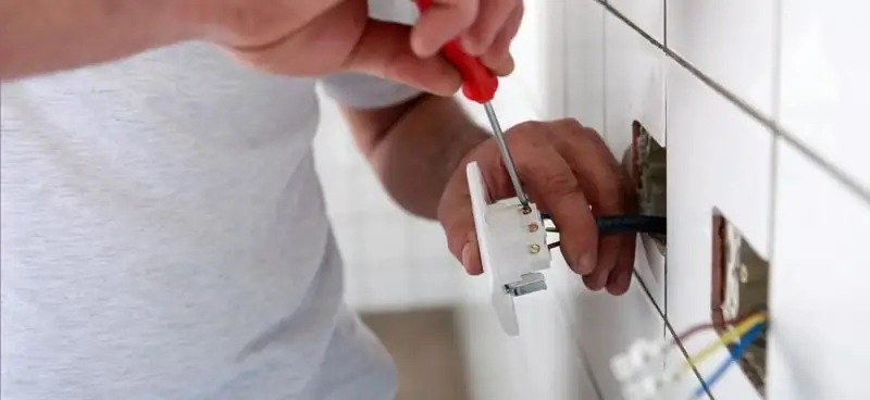
We connect the ends of the phase and zero to the corresponding contacts and tighten the screws with a screwdriver. The phase, as a rule, has a brown wire color, and zero is blue.

Connecting the socket We connect the phase and zero wires to the corresponding contacts and clamp them with screws
- We connect the ground wire under the appropriate screw.
-
We carefully lay the wires and insert the socket tightly into the hole, clamping the screws of the mounting plates evenly and in turn.

Mount the socket In the box, the socket is fastened by screwing in the corresponding screws that move the mounting plates apart
-
Additionally, we attach the socket to the box using self-tapping screws.

Additional mount The socket is additionally attached to the box using self-tapping screws
-
Install the frame and decorative trim.

Installing the faceplate The decorative strip is fixed with a screw
Checking the functionality of the socket
You can use a multimeter to check that the outlet is functioning. The device allows you to find out not only the operability of the installed element, but also to find out what voltage is currently in the mains. To do this, just follow these steps:
- We turn on the machine (switch).
- We set the multimeter to the measurement limit of 750 V AC, i.e. AC voltage.
- We insert the probes into the outlet, holding them by the insulated part. Under no circumstances should you touch the bare part of the probes, this will lead to electric shock.
- On the screen of the device, we get the current voltage in the mains.
Video: how to measure the voltage in the network
If you do not have a voltage tester, you can use an indicator screwdriver. The tool allows you to identify the voltage in the network by the presence of a phase. To do this, it is enough to clamp the contact on the screwdriver handle with your thumb, and then, one by one, bring the working part of the tool to the socket contacts. If there is voltage in the network, an indicator on one of the contacts of the socket in the screwdriver will light up, which will indicate the presence of a phase. There should be no indication on the second contact, since it corresponds to zero.

You can check the presence of voltage in the network with an indicator screwdriver
Working with electrical wiring requires certain skills and abilities. However, if you have at least basic knowledge in the field of electrical engineering and the necessary tools, then observing safety precautions and step-by-step instructions, you can install sockets in the kitchen yourself.
Recommended:
The Location Of The Sockets In The Kitchen: Placement Height, How Many And Where Needed, Photos, Diagrams
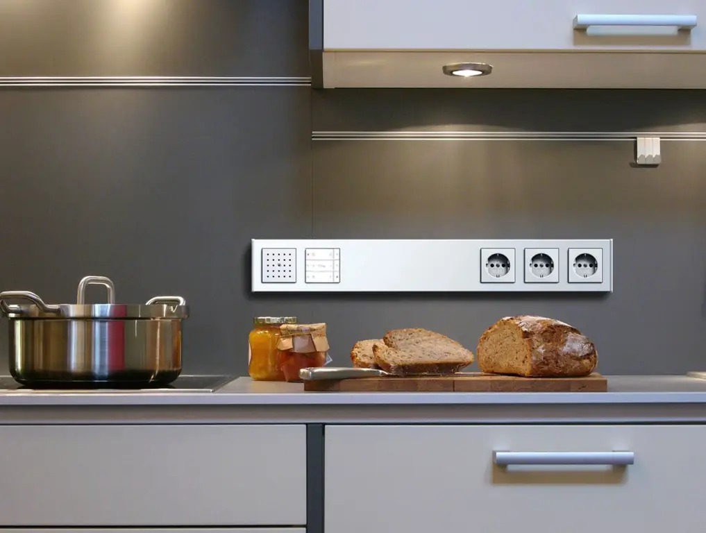
Rules and regulations for the location of outlets in the kitchen. Calculation of the required number of outlets. Drawing up an electrical wiring diagram. Types and installation of sockets
Retractable Recessed Sockets For Worktops: Characteristics And Installation
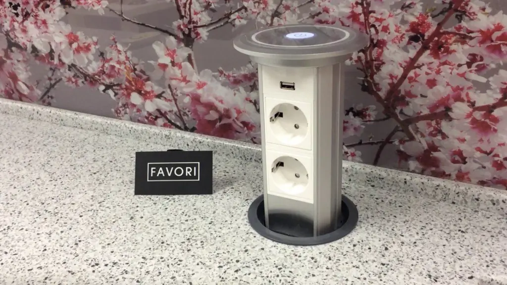
Varieties of built-in movable sockets, their advantages and disadvantages. Installation procedure and operating conditions
How To Set Up An Internet Connection On A Computer: Setting Up A Network And Automatic Connection At System Startup
How to set up an Internet connection on a PC with Windows XP, 7, 8 and 10, as well as Linux and Ubuntu. Automatic internet connection when Windows starts
PPPOE Connection Protocol: What Is It, Setting Up A High-speed Connection For Windows 7, 10, Possible Errors
What is PPPoE protocol: pros and cons, principle of operation. How to configure this connection on Windows 7 and 10. What to do if an error appears
How To Fix The Error Your Connection Is Not Secure When Establishing A Connection On Mozila Firefox

Eliminate the error of establishing a secure connection in Mozilla Firefox. Verified instructions
