Table of contents:
- Author Bailey Albertson [email protected].
- Public 2023-12-17 12:53.
- Last modified 2025-06-01 07:32.
Reliable backbone: calculation of the gable roof rafter system
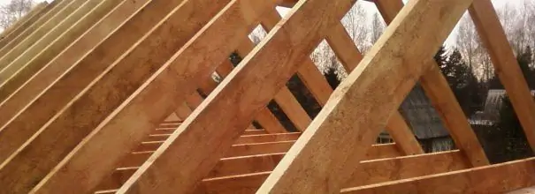
A gable roof is formed on the basis of a frame that combines elementary structure and unsurpassed reliability. But the backbone of the roof in two rectangular slopes can boast of these advantages only in the case of a careful selection of rafter legs.
Content
-
1 Parameters of the gable roof truss system
- 1.1 Rafter length
-
1.2 Cross-section of rafter legs
1.2.1 Table: cross-section of rafters depending on length and pitch
-
1.3 Variable effect on the rafter system
- 1.3.1 Table: Guideline value of wind pressure
- 1.3.2 Table: value of the coefficient k
-
1.4 Permanent loads
1.4.1 Table: weight of roofing materials per 1 m²
- 1.5 Number of bars
-
2 Step of the beams of the roof supporting structure
2.1 Table: pitch of rafters depending on length and section
-
3 Formulas for calculating the rafter system of a gable roof
- 3.1 Table: nominal dimensions of thickness and width of sawn timber (mm)
-
3.2 Example of structural analysis
3.2.1 Video: detailed calculation of the rafter system
Parameters of the gable roof rafter system
It is worth starting the calculations if you understand that the rafter system of a gable roof is a complex of triangles, the most rigid elements of the frame. They are assembled from boards, the size of which plays a special role.
Rafter length
The formula a² + b² = c², derived by Pythagoras, will help to determine the length of solid boards for the rafter system
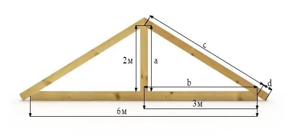
The length of the rafter can be found by knowing the width of the house and the height of the roof.
The "a" parameter indicates the height and is self-selected. It depends on whether the under-roof space will be residential; it also has certain recommendations if an attic is planned.
Behind the letter "b" is the width of the building, divided in two. And "c" represents the hypotenuse of the triangle, that is, the length of the rafter legs.
Let's say that the width of half of the house is three meters, and it is decided to make the roof two meters high. In this case, the length of the rafter legs will reach 3.6 m (c = √a² + b² = 4 + √9 = √13≈3.6).
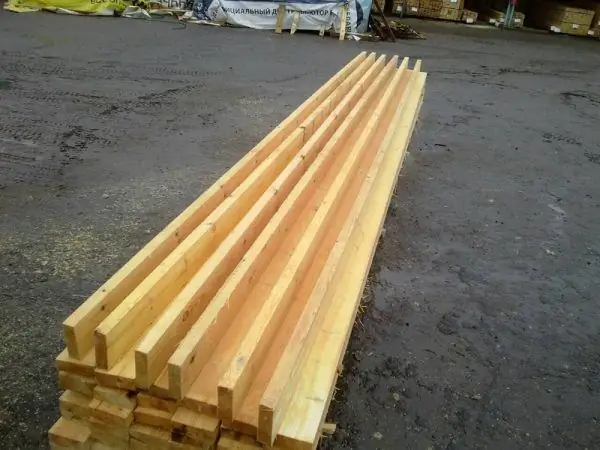
The six-meter rafter is the longest, therefore it is suitable as a rafter leg
The maximum length of a bar used as a rafter leg is 6 m. If a durable board of greater length is required, then they resort to the splicing technique - nailing a piece from another bar to the rafter leg.
Cross-section of rafter legs
For various elements of the rafter system, there are standard sizes:
- 10x10 or 15x15 cm - for the Mauerlat bar;
- 10x15 or 10x20 cm - for the rafter leg;
- 5x15 or 5x20 cm - for running and strut;
- 10x10 or 10x15 cm - for the rack;
- 5x10 or 5x15 cm - for the bed;
- 2x10, 2.5x15 cm - for crates.
The thickness of each part of the roof supporting structure is determined by the load that it has to experience
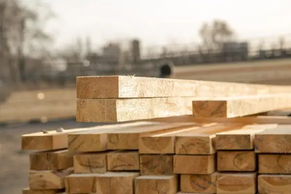
A beam with a section of 10x20 cm is ideal for creating a rafter leg
The cross-section of the rafter legs of a gable roof is affected by:
- load on roof slopes;
- the type of construction raw materials, because the "aging" of logs, ordinary and glued beams differs;
- rafter leg length;
- the type of wood from which the rafters were planed;
- the length of the gap between the rafter legs.
The rafter pitch affects the cross-section of the rafter legs most significantly. An increase in the distance between the beams entails increased pressure on the supporting structure of the roof, and this obliges the builder to use thick rafter legs.
Table: cross-section of rafters depending on length and pitch
| Rafter legs length (m) | Distance between rafters (m) | Cross-section of the rafter system (cm) |
| Less than 3 | 1,2 | 8 × 10 |
| Less than 3 | 1.8 | 9 × 10 |
| 3 to 4 | one | 8 × 16 |
| 3 to 4 | 1.4 | 8 × 18 |
| 3 to 4 | 1.8 | 9 × 18 |
| Until 6 | one | 8 × 20 |
| Until 6 | 1.4 | 10 × 20 |
Variable effect on the rafter system
The pressure on the rafter legs is constant and variable.
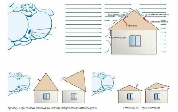
The wind tends to overturn or raise the roof, so it is important to make all the calculations correctly
The variable wind load on the rafters is determined by the formula W = Wo × kxc, where W is the wind load indicator, Wo is the value of the wind load characteristic for a certain part of Russia, k is a correction factor due to the height of the structure and the nature of the terrain, and c is the aerodynamic coefficient.
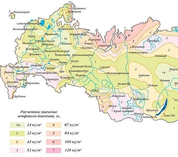
The calculation of the wind pressure on the roof is based on the location of the house
The normative value of wind pressure is recognized by map 3 of Appendix 5 in SNiP 2.01.07-85 and a special table. The coefficient taking into account the change in wind pressure with height is also standardized.
Table: guideline value of wind pressure
| Wind areas | Ia | I | II | III | IV | V | VI | Vii |
| Wo, kPa | 0.17 | 0.23 | 0.30 | 0.38 | 0.48 | 0.60 | 0.73 | 0.85 |
| Wo, kg / m² | 17 | 23 | thirty | 38 | 48 | 60 | 73 | 85 |
Table: value of the coefficient k
| Height | Open area | Closed area with houses over 10 m high | Urban areas with buildings above 20 m |
| up to 5m | 0.75 | 0.5 | 0,4 |
| from 5 to 10m | 1.0 | 0.65 | 0,4 |
| from 10 to 20m | 1.25 | 0.85 | 0.53 |
It is not just the terrain that affects the wind load. The area of housing is of great importance. Behind a wall of tall buildings, the house is almost not threatened, but in open space the wind can become a serious enemy for it.
The snow load on the rafter system is calculated using the formula S = Sg × µ, that is, the weight of the snow mass per 1 m² is multiplied by a correction factor, which reflects the degree of roof slope
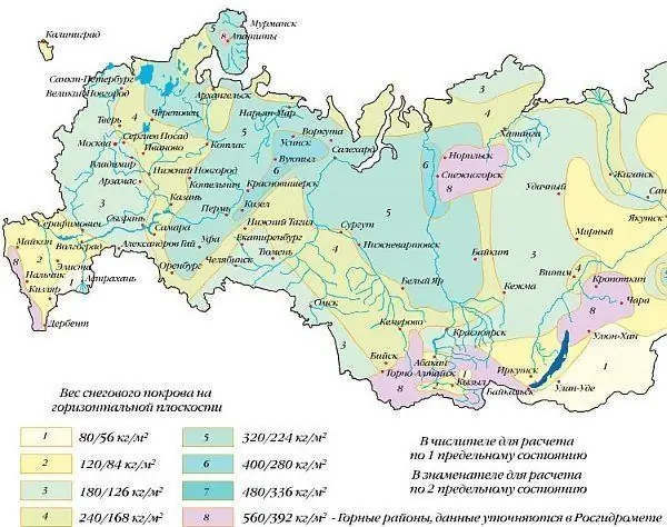
The snow load on the roof depends on where the house is located
The correction factor, if the roof slopes are inclined by less than 25 °, is equal to one. And in the case of a roof slope of 25-60 °, this figure decreases to 0.7.
Constant loads
Loads acting continuously are considered to be the weight of the roofing cake, including the sheathing, insulation, films and finishing materials for arranging the attic.
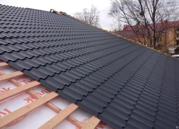
The roofing cake creates constant pressure on the rafters
Roof weight is the sum of the weight of all materials used in the construction of the roof. On average, it is equal to 40-45 kg / sq. M. According to the rules, 1 m² of the rafter system should not account for more than 50 kg of the weight of roofing materials.
Table: weight of roofing materials per 1 m²
| Type of roof topcoat | Weight in kg per 1 m2 |
| Rolled bitumen-polymer cloth | 4-8 |
| Bituminous-polymer soft tile | 7-8 |
| Ondulin | 3-4 |
| Metal roof tiles | 4-6 |
| Decking, seam roofing, galvanized metal sheets | 4-6 |
| Cement-sand tile | 40-50 |
| Ceramic tiles | 35-40 |
| Slate | 10-14 |
| Slate roof | 40-50 |
| Copper | 8 |
| Green roof | 80-150 |
| Rough flooring | 18-20 |
| Lathing | 8-10 |
| The rafter system itself | 15-20 |
Number of beams
How many rafters will be needed to equip the gable roof frame is set by dividing the width of the roof by a step between the beams and adding one to the resulting value. It denotes an additional rafter that will need to be placed on the edge of the roof.
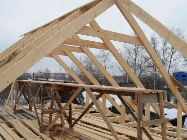
The rafter system of a gable roof is a structure made of a certain number of rafters
The pitch of the beams of the roof supporting structure
To determine the distance between the beams of the roof supporting structure, you should pay close attention to such points as:
- weight of roofing materials;
- the length and thickness of the timber - the future rafter leg;
- degree of roof slope;
- level of wind and snow loads.
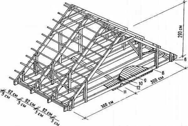
After 90-100 cm, rafters are usually placed in the case of choosing a light roofing material
A step of 60-120 cm is considered normal for rafter legs. The choice in favor of 60 or 80 cm is made in the case of building a roof inclined by 45˚. The same small step should be, if desired, to cover the wooden roof frame with heavy materials such as ceramic tiles, asbestos-cement slate and cement-sand tiles.
Table: rafter pitch depending on length and section
| Length of timber-rafters (m) | Clearance between rafters (m) | ||
| one | 1.4 | 1.8 | |
| Rafters section (cm) | |||
| Less than 2.8 | 4 × 12.5 | 4 × 17.5 | 4 × 20 |
| 2.8-3.5 | 4 × 17.5 | 4 × 20 | 4 × 22.5 |
| 3.5-4.2 | 4 × 20 | 4 × 25 | 5 × 25 |
| 4.2-5 | 4 × 22.5 | 6 × 25 | 7.5 × 25 |
| More than 5 | 6 × 25 | 7.5 × 25 | 10 × 25 |
Formulas for calculating the rafter system of a gable roof
The calculation of the rafter system is reduced to establishing the pressure on each beam and determining the optimal section.
When calculating the gable roof truss system, proceed as follows:
- According to the formula Qr = AxQ, they find out what the load per linear meter of each rafter leg is. Qr is the distributed load per linear meter of the rafter leg, expressed in kg / m, A is the distance between the rafters in meters, and Q is the total load in kg / m².
- Go to the definition of the minimum cross-section of the timber-rafter. To do this, study the data of the table entered in GOST 24454-80 “Lumber of coniferous species. Dimensions ".
- Based on the standard parameters, the section width is selected. And the section height is calculated using the formula H ≥ 8.6 · Lmax · sqrt (Qr / (B · Rben)), if the roof slope is α 30 °. H is the height of the section in cm, Lmax is the working section of the rafter leg of maximum length in meters, Qr is the distributed load per linear meter of the rafter leg in kg / m, B is the width of the section, cm, Rben is the resistance of wood to bending, kg / cm². If the material is made from pine or spruce, then Rben can be equal to 140 kg / cm² (1 grade of wood), 130 kg / cm 2 (2 grade) or 85 kg / cm 2 (3 grade). Sqrt is the square root.
- Check if the deflection value complies with the standards. It should not be more than the number that is obtained by dividing L by 200. L is the length of the working section. Correspondence of the deflection value to the ratio L / 200 is feasible only if the inequality is correct 3.125 · Qr · (Lmax) ³ / (B · H³) ≤ 1. Qr denotes the distributed load per linear meter of the rafter leg (kg / m), Lmax - the working area of the rafter leg maximum length (m), B - section width (cm), and H - section height (cm).
- When the above inequality is violated, the B and H scores increase.
Table: nominal dimensions of thickness and width of sawn timber (mm)
| Board thickness - section width (B) | Board width - section height (H) | ||||||||
| 16 | 75 | 100 | 125 | 150 | - | - | - | - | - |
| 19 | 75 | 100 | 125 | 150 | 175 | - | - | - | - |
| 22 | 75 | 100 | 125 | 150 | 175 | 200 | 225 | - | - |
| 25 | 75 | 100 | 125 | 150 | 175 | 200 | 225 | 250 | 275 |
| 32 | 75 | 100 | 125 | 150 | 175 | 200 | 225 | 250 | 275 |
| 40 | 75 | 100 | 125 | 150 | 175 | 200 | 225 | 250 | 275 |
| 44 | 75 | 100 | 125 | 150 | 175 | 200 | 225 | 250 | 275 |
| 50 | 75 | 100 | 125 | 150 | 175 | 200 | 225 | 250 | 275 |
| 60 | 75 | 100 | 125 | 150 | 175 | 200 | 225 | 250 | 275 |
| 75 | 75 | 100 | 125 | 150 | 175 | 200 | 225 | 250 | 275 |
| 100 | - | 100 | 125 | 150 | 175 | 200 | 225 | 250 | 275 |
| 125 | - | - | 125 | 150 | 175 | 200 | 225 | 250 | - |
| 150 | - | - | - | 150 | 175 | 200 | 225 | 250 | - |
| 175 | - | - | - | - | 175 | 200 | 225 | 250 | - |
| 200 | - | - | - | - | - | 200 | 225 | 250 | - |
| 250 | - | - | - | - | - | - | - | 250 | - |
An example of a structural analysis
Suppose that α (angle of inclination of the roof) = 36 °, A (distance between the rafters) = 0.8 m, and Lmax (working section of the rafter leg of maximum length) = 2.8 m. Material from first grade pine is used as the beams, which means that Rben = 140 kg / cm².
Cement-sand tiles have been chosen for the roofing and therefore the weight of the roof is 50 kg / m². The total load (Q) experienced by each square meter is 303 kg / m². And for the construction of the rafter system, beams with a thickness of 5 cm are used.
Hence the following computational steps follow:
- Qr = A · Q = 0.8 · 303 = 242 kg / m - distributed load per linear meter of rafter timber.
- H ≥ 9.5 Lmax sqrt (Qr / B Rben).
- H ≥ 9.5 2.8 sqrt (242/5 140).
- 3.125 · Qr · (Lmax) ³ / B · H³ ≤ 1.
- 3.125 · 242 · (2.8) ³ / 5 · (17.5) ³ = 0.61.
- H ≥ (approximate height of the rafter section).
In the table of standard sizes, you need to find the height of the rafter section close to the indicator of 15.6 cm. A parameter equal to 17.5 cm is suitable (with a section width of 5 cm).
This value is quite consistent with the deflection indicator in the regulatory documents, and this is proved by the inequality 3.125 · Qr · (Lmax) ³ / B · H³ ≤ 1. Substituting the values (3.125 · 242 · (2.8) ³ / 5 · (17, 5) ³), it turns out that 0.61 <1. We can conclude that the section of the lumber is chosen correctly.
Video: detailed calculation of the rafter system
The calculation of the gable roof rafter system is a whole complex of calculations. In order for the bars to cope with the task assigned to them, the builder needs to accurately determine the length, quantity and cross-section of the material, find out the load on it and find out what should be the step between the rafters.
Recommended:
The Structure Of The Roof Of A Wooden House, Including The Main Nodes Of The Roof, As Well As What Material Is Better To Use
Roof device of a wooden house. The main units, elements and types of roofing. Insulation, decoration, repair and replacement of the roof of a wooden house
Roofing Cake For A Soft Roof, As Well As The Features Of Its Structure And Installation, Depending On The Type Of Roof And The Purpose Of The Room
What is a cake under a soft roof. Features of its device and installation. How to arrange a roofing cake from roll and piece materials
Roof Drip, Its Structure And Purpose, As Well As Calculation And Installation Features
What are roof drippers and how they differ from eaves. Is it obligatory to install drippers. Device and installation
The Rafter System Of A Gable Roof For Corrugated Board, Including Its Scheme And Design, As Well As Installation Features
The rafter system of the gable roof, its design and calculation, as well as the main components. Stages of construction, step of rafters and installation of crate for corrugated board
Gable Roof Rafter System, Including Its Layout And Design, As Well As Installation Features
Features of the design of a gable roof. Material selection criteria. Installation of a gable rafter system. Types of connections of the main nodes of the roof
